Electrical installation
56 © SICK AG · Division Auto Ident · Germany · Subject to change without notice 8013796/UL20/2010-09-27
Operating Instructions
Laser Measurement Systems of the LMS500 Product Family
Chapter 5
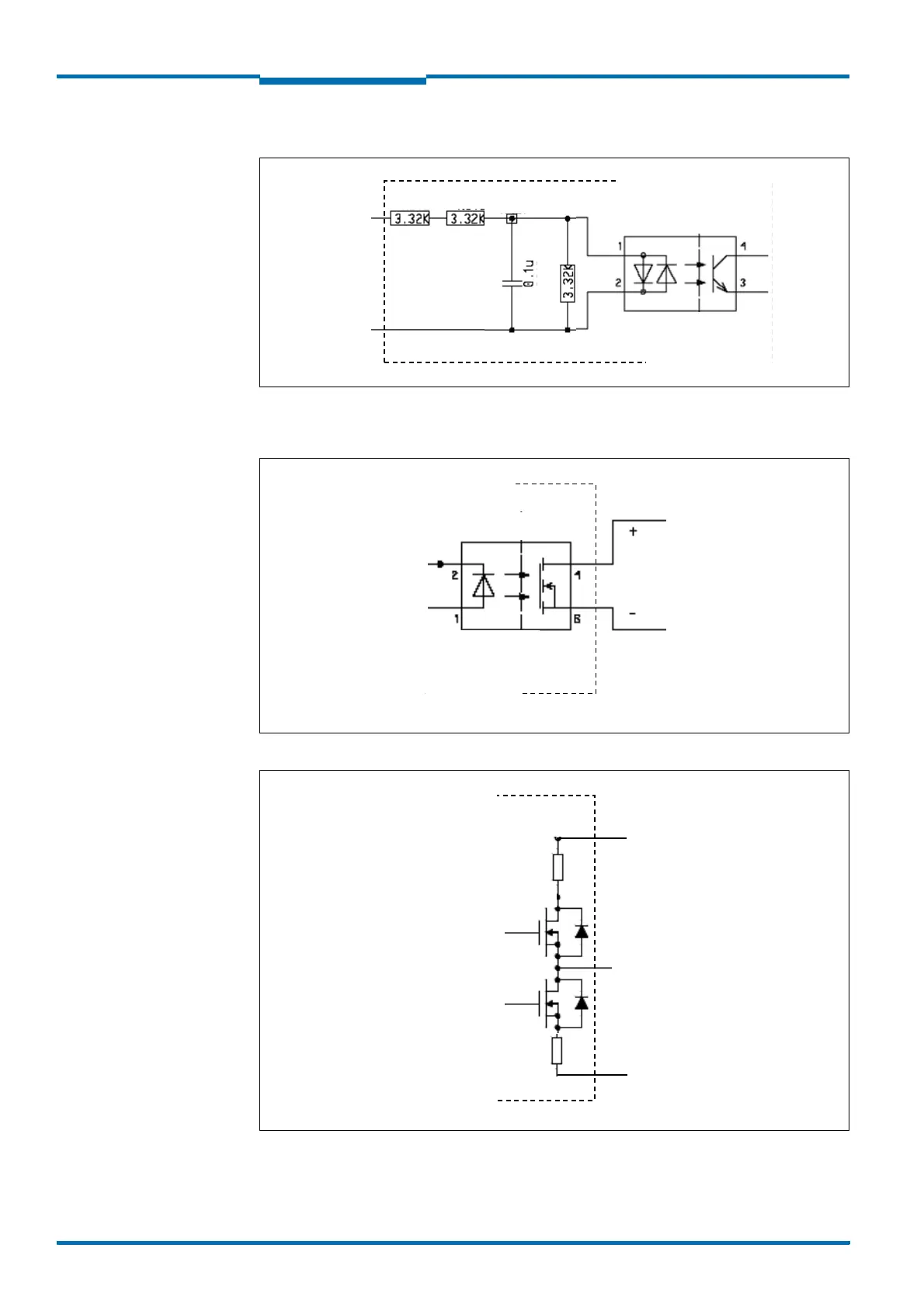
Wiring inputs In 1…4
Fig. 42: Wiring inputs In 1…4
Connection of the outputs of the LMS to a PLC
Fig. 43: Connection of the outputs to a PLC (active low)
Fig. 44: Connection of the outputs to a PLC (active high)
LMS
Out 3…6
V
CC
ext.
PLC
GND ext.

 Loading...


