Operating Instructions
LMS500 Product Family
Electrical installation
8013796/UL20/2010-09-27 © SICK AG · Division Auto Ident · Germany · Subject to change without notice 55
Chapter 5
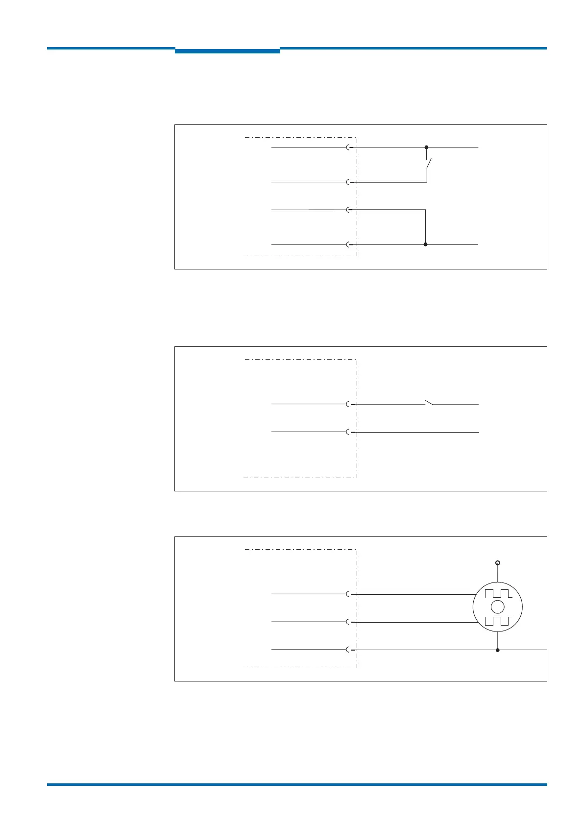
5.4.5 Wiring of inputs and outputs on the LMS
C
onnecting digital inputs as non-floating
Fig. 39: Connecting digital inputs as non-floating
Important The inputs require a switching voltage of at least 11 V. For this reason the supply voltage
must be at least 11 V.
Connecting digital inputs as floating
Fig. 40: Connecting digital inputs as floating
Wiring encoder inputs
Fig. 41: Wiring encoder inputs
LMS
IN1
IN1 GND
GND
V
S
11 V … 30 V
External switch
LMS
IN1
IN1 GND
External signal source
U
E
11 V … 30 V
LMS
INC1 IN3
INC2 IN4
GND
V
S
Encoder
GND encoder
0°
90°

 Loading...


