Electrical installation
48 © SICK AG · Division Auto Ident · Germany · Subject to change without notice 8013796/UL20/2010-09-27
Operating Instructions
Laser Measurement Systems of the LMS500 Product Family
Chapter 5
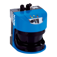
5.2.1 Connections of the LMS500
“Ethernet” connection M12×4, socket
Terminal Signal Function
1 24 V SYS Supply voltage LMS
2 GND SYS Ground LMS
3 24 V EXT
4GND EXT
5 OUT 1 Digital output 1
6 OUT 2 Digital output 2
7 OUT 3 Digital output 3
8 OUT 4 Digital output 4
9 OUT 5 Digital output 5
10 OUT 6 Digital output 6
11 CAN H CAN-BUS High
12 GND CAN HST Ground CAN host
13 CAN L CAN-BUS Low
14 SHIELD Shield
15 Reserved Do not use!
16 Reserved Do not use!
17 IN3 Digital input 3
18 IN4 Digital input 4
19 IN34EXT
20 IN12EXT
21 IN1 Digital input 1
22 IN2 Digital input 2
23 RTS TDP
24 TXD TDN
25 GND CAN HST Ground CAN host
26 RXD RDN
27 CTS RDP
28 SHIELD Shield
Tab. 9: Terminal assignment of the LMS500
Pin Signal Function
1 Ethernet_TX+ Ethernet interface
2 Ethernet_RX+ Ethernet interface
3 Ethernet_TX– Ethernet interface
4 Ethernet_RX– Ethernet interface
Tab. 10: Pin assignment of the “Ethernet” connection on the LMS500

 Loading...