Operating Instructions
LMS500 Product Family
Electrical installation
8013796/UL20/2010-09-27 © SICK AG · Division Auto Ident · Germany · Subject to change without notice 49
Chapter 5
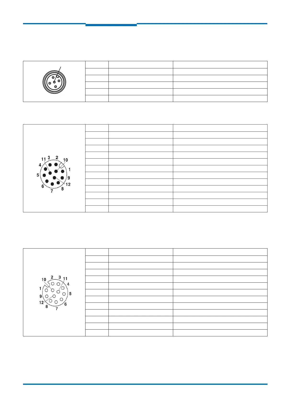
5.2.2 Connections of the LMS511
“
Power” connection M12×5, plug
Communication connection M12×12, plug
“I/O” connection M12×12, socket
Pin Signal Function
1V
S
LMS supply voltage
2V
s
heat. Supply voltage for the heating
3 GND Ground
4 – Not assigned
5 GND heat. Ground heating
Tab. 11: Pin assignment of the “Power” connection on the LMS511
Pin Signal Function
1
1)
V
CC
Out 1+2
2 RS422 RxD- Serial RSF422 host interface (receiver)
3
1)
Out 1
4 RS422 CAN GND Ground Serial RS-422 and CAN
5
1)
Out 2
6
1)
NC Not connected
7 RS422 TxD- Serial RSF422 host interface (sender)
8
1)
NC Not connected
9 RS422 RxD+ Serial RSF422 host interface (receiver)
10 RS422 TxD+ Serial RSF422 host interface (sender)
11
1)
CAN Low CAN-BUS Low
12
1)
CAN High CAN-BUS High
Tab. 12: Pin assignment of the “RSF232” connection on the LMS511
1) Available from December 2010.
Pin Signal Function
1V
CC
Out 3-6
2
1)
GND In 1+2
3
1)
In 1
4 GND In 3+4
5
1)
In 2
6In 3
7GND Out 3-6
8In 4
9
2)
Out 3
10
1)
Out 4
11 Out 5
12 Out 6
Tab. 13: Pin assignment of the “I/O” connection on the LMS511
1) Available from December 2010.
2) SOPAS software must be configured as Out 1. From December 2010 SOPAS will change to Out 3.

 Loading...


