Electrical installation
54 © SICK AG · Division Auto Ident · Germany · Subject to change without notice 8013796/UL20/2010-09-27
Operating Instructions
Laser Measurement Systems of the LMS500 Product Family
Chapter 5
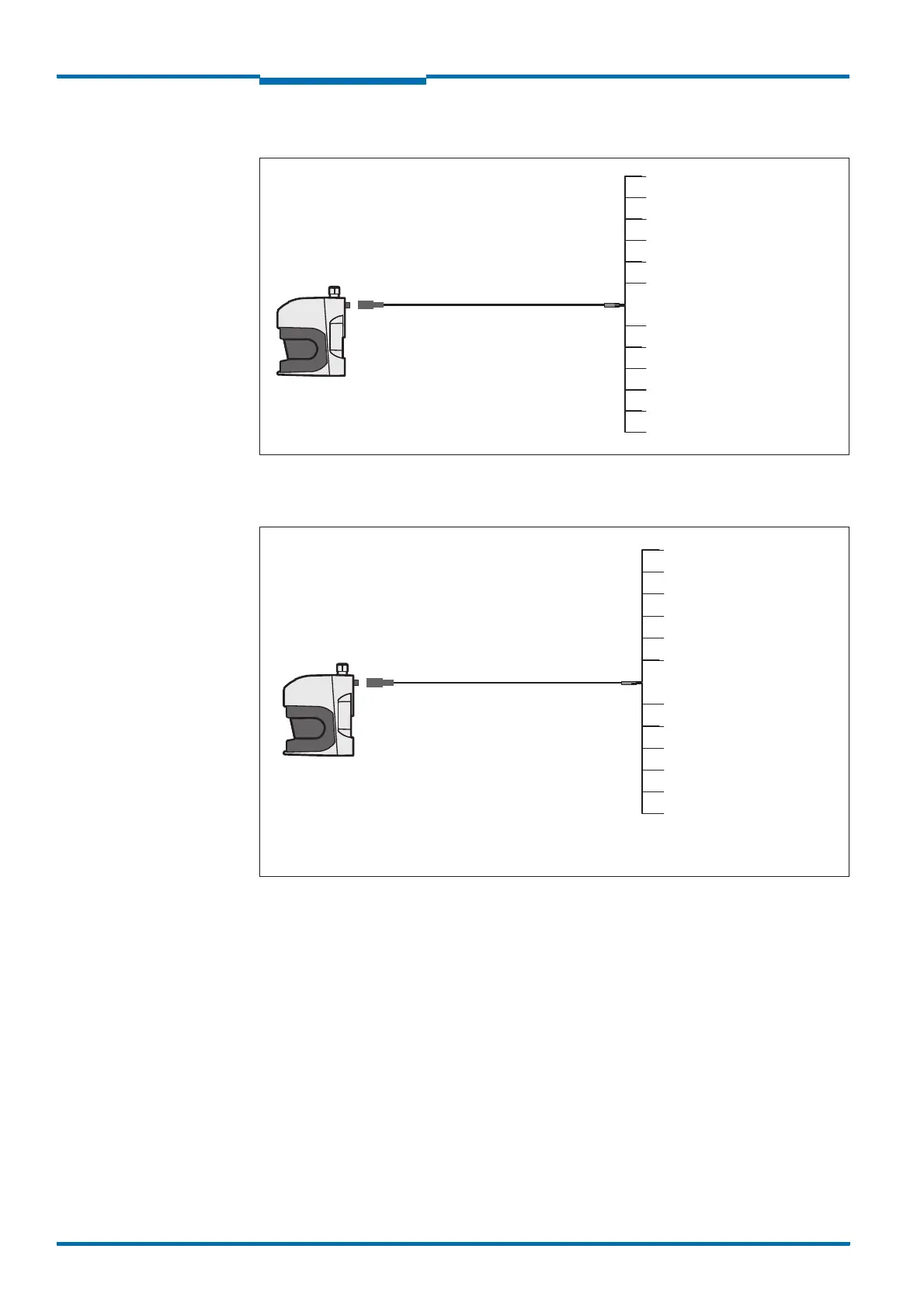
Communication connection on the LMS511
Fig. 37: LMS511: Communication connection
“I/O” connection on the LMS511
Fig. 38: LMS511: “I/O” connection
LMS
Yellow = NC
Brown = V
CC
Out 1+2 24 V
P
art no. 6042735, 5 m (16.40 ft)
Part no. 6042736, 10 m (32.81 ft)
P
art no. 6042737, 20 m (65.62 ft)
Socket
M12×12 pin
Grey = NC
White = Out 1
Green = RS422 CAN GND 0V
Pink = Out 2
Red = RS422 RxD+
Blue = RS422 RxD-
Black = RS422 TxD-
Violet = RS422 TxD+
Green/Pink = CAN Low
Red/Blue = CAN High
LMS
Yellow = In 3
Green = GND In 3+4
Part no. 6042732, 5 m (16.40 ft)
Part no. 6042733, 10 m (32.81 ft)
Part no. 6042734, 20 m (65.62 ft)
Plug
M12×8 pin
Black = GND Out 3-6
White = In 1
Pink = In 2
Grey = In 4
Violet = Out 4
Red = Out 3*
Blue = GND In 1+2
Brown = V
CC
Out 3-6
Red/Blue = Out 6
Green/Pink = Out 5
* SOPAS software must be configured as Out 1.
After Dec. 2010 SOPAS will change to Out 3.

 Loading...


