Operating Instructions
LMS500 Product Family
Electrical installation
8013796/UL20/2010-09-27 © SICK AG · Division Auto Ident · Germany · Subject to change without notice 51
Chapter 5
5.4 Perform electrical installation on the LMS
Lay all cables such that there is no risk of tripping and all cables are protected against
damage.
5.4.1 Equipment
• tool set
• digital multimeter (current/voltage measurement)
5.4.2 Connection on the USB auxiliary interface and the Ethernet interface of the
LMS500/511
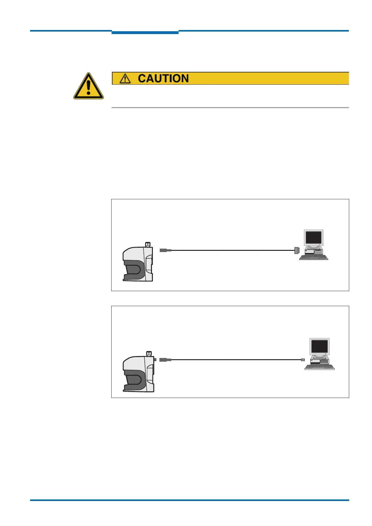
Pre-assembled cables are available to configure the LMS via the USB auxiliary interface and
via the Ethernet interface.
Fig. 34: LMS500/511: USB connection at the auxiliary interface
Fig. 35: LMS500/511: Ethernet connection using the Ethernet cable
24 V DC
Plug
Socket
USB
Mini-USB
Part no. 6042517, 3 m (9.84 ft)
LMS
PC
LMS
24 V DC
M12×4 pin
RJF45
8 pin
Plug
Part no. 6034415, 5 m (16.40 ft)
Part no. 6030928, 10 m (32.81 ft)
Part no. 6036158, 20 m (65.62 ft)
Plug
PC
 Loading...


