Mounting
40 © SICK AG · Division Auto Ident · Germany · Subject to change without notice 8013796/UL20/2010-09-27
Operating Instructions
Laser Measurement Systems of the LMS500 Product Family
Chapter 4
4.3 Mounting steps
Special features to note during mounting:
• Mount the LMS such that it is protected from moisture, dirt, damage and direct sunlight.
• Ensure that the entire field of view of the LMS is not restricted.
• Mount the laser measurement system such that the indicators are easy to see.
• Always mount the LMS so that there is still enough space for mounting and removing
the system plug.
• Avoid excessive shock and vibration loading on the laser measurement system.
• On applications that suffer from heavy vibration, prevent the fixing screws from coming
loose using screw locking devices (see section 9.1 “Data sheet LMS laser
measurement system” on page 67).
• Regularly check the tightness of the fixing screws.
• Pay attention to the maximum torque for the fixing screws on the LMS:
– M6 on rear = max. 12 Nm
– M8 on side = max. 16 Nm
The LMS can be fastened in the following ways:
• direct mounting without mounting kit
• mounting with mounting kit 1
• mounting with mounting kit 2 (only in conjunction with mounting kit 1)
• mounting with mounting kit 3 (only in conjunction with mounting kits 1 and 2)
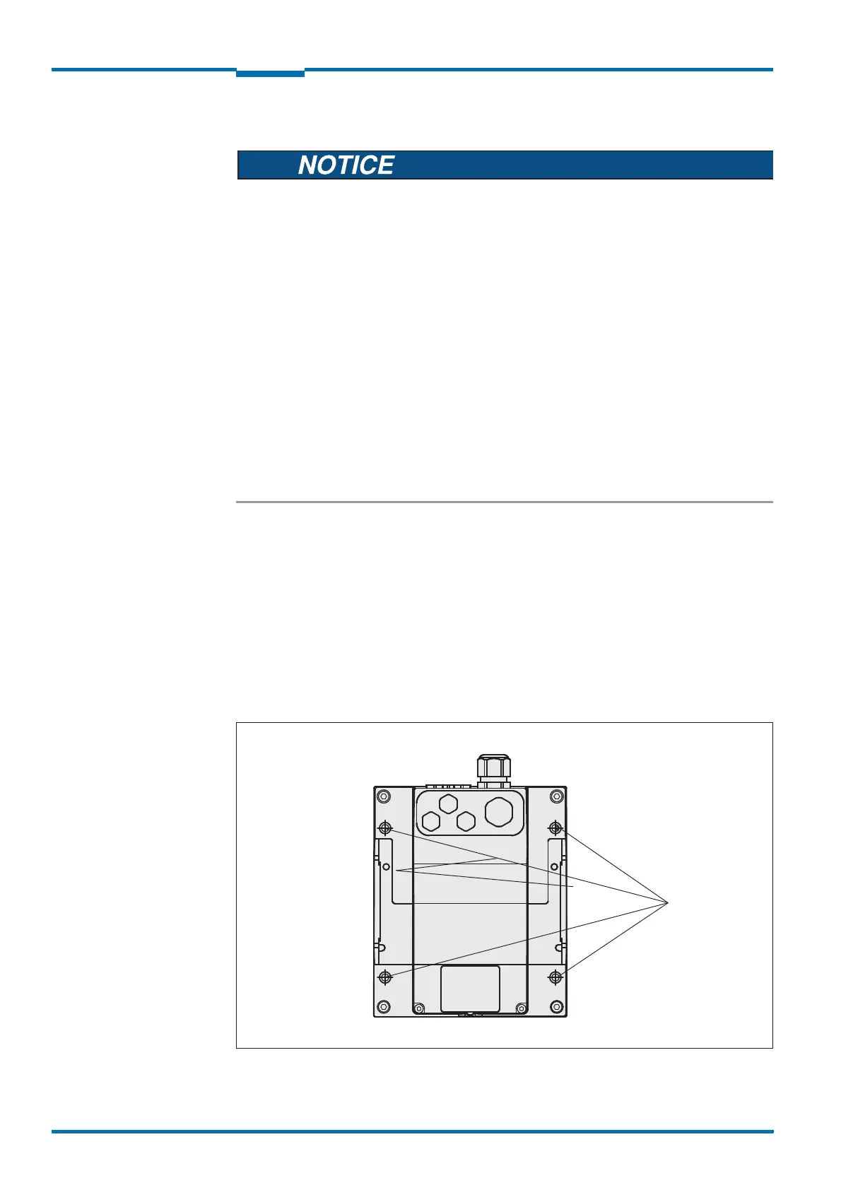
4.3.1 Direct mounting
The LMS has four M6×8 threaded holes on the rear. Using them you can mount the LMS
directly on the intended mounting surface.
Fig. 22: Direct mounting
 Loading...


