Parameter Value Factory settings
Q1 SP1 teach-in (auto) Setting the switching point
OD2000-030:
-5.04mm ... +5.75mm
OD2000-050:
-10.10mm ... +11.50mm
OD2000-245:
-176.75mm ... +189.00mm
OD2000-350:
-252.50mm ... +271.00mm
OD2000-700:
-505.00mm ... +550.00mm
SP1: 0.00mm
Q1 SP1 teach-in (manual)
Q1 SP2 teach-in (auto) SP2:
OD2000-030: +5mm
OD2000-050: +10mm
OD2000-245: +175mm
OD2000-350: +250mm
OD2000-700: +500mm
Q1 SP2 teach-in (manual)
Q1 Switch point logic High-active
Low-active
High-active
Q1 Timer mode Off
Switch-on delay
Switch-off delay
Switch-on/off delay
Impulse (one shot)
Off
Q1 Timer setup 1ms ... 30,000ms 1ms
Q1 Hysteresis 0mm ... 2,147.48mm OD2000-030: 0.1mm
OD2000-050: 0.2mm
OD2000-245: 0.5mm
OD2000-350: 1mm
OD2000-700: 1.5mm
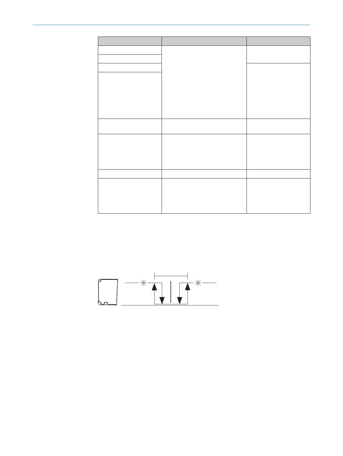
7.4.3.4 Q1 Window (SP1:ObSB) menu
Set a background as a reference. If the reference background is not detected (nor‐
mally open contact: High-active switching point logic) or if the reference background is
detected (normally closed contact: Low-active switching point logic), a signal is output. In
the ObSB output mode, all objects deviating from the background are detected. Objects
that are reflective or black are also detected.
Figure 14: Object between device and background (N/O contact: High-active, PNP)
1
Minimum
2
Tolerance around switching point
3
Maximum
4
Switching point (reference background)
7 OPERATION
34
O P E R A T I N G I N S T R U C T I O N S | OD2000 8026231/1I18/2023-01-05 | SICK
Subject to change without notice