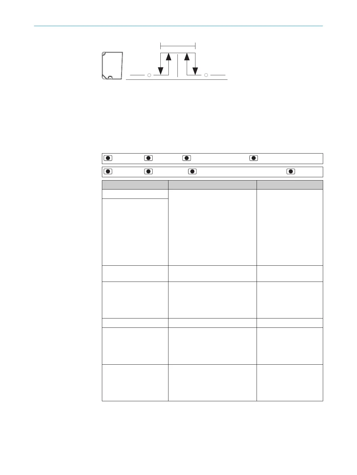
Figure 15: Object between device and background (N/C contact: Low-active, PNP)
1
Minimum
2
Tolerance around switching point
3
Maximum
4
Switching point (reference background)
Selecting output mode and setting parameters
> Q1 Output > > Q1 Mode > > Q1 Window (SP1:ObSB) >
> Q1 Output > > Parameter > > Select option, teach-in or set value >
Parameter Value Factory setting
Q1 SP1 teach-in (auto) Setting the switching point
OD2000-030:
-5.04mm ... +5.75mm
OD2000-050:
-10.10mm ... +11.50mm
OD2000-245:
-176.75mm ... +189.00mm
OD2000-350:
-252.50mm ... +271.00mm
OD2000-700:
-505.00mm ... +550.00mm
0.00mm
Q1SP1 teach-in (manual)
Q1 Switch point logic High-active
Low-active
High-active
Q1 Timer mode Off
Switch-on delay
Switch-off delay
Switch-on/off delay
Impulse (one shot)
Off
Q1 Timer setup 1ms ... 30,000ms 1ms
Q1 Hysteresis 0mm ... 2,147.48mm OD2000-030: 0.1mm
OD2000-050: 0.2mm
OD2000-245: 0.5mm
OD2000-350: 1mm
OD2000-700: 1.5mm
Q1 Tolerance 0mm ... 2,147.48mm OD2000-030: 1mm
OD2000-050: 1mm
OD2000-245: 4mm
OD2000-350: 4mm
OD2000-700: 4mm
7.4.3.5 Q1 Alarm menu
As long as no measurement is possible, a constant switching signal is issued at the
output. This function can be used, for example, to evaluate the measured value at the
analog output.
OPERATION 7
8026231/1I18/2023-01-05 | SICK O P E R A T I N G I N S T R U C T I O N S | OD2000
35
Subject to change without notice