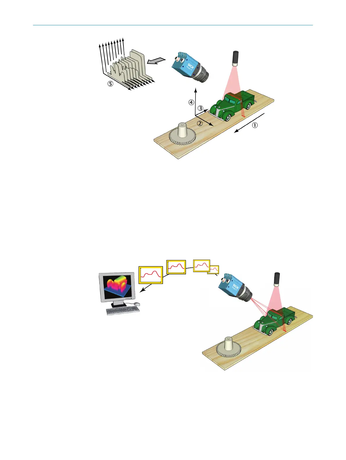
Figure 3: Measuring the range of a cross-section of an object.
1
Transportation direction
2
X (width)
3
Y (negative transport direction)
4
Z (range)
5
Profiles
By default, the range measurement values from the camera are not calibrated – that is:
•
X and Z (range) coordinates are represented by column and row positions on the
sensor, instead of real world positions and distances.
•
Y coordinates are represented for example by the sequence number of the meas‐
urement, or by the encoder value for when the profile was captured.
Figure 4: Profiles are sent from the Ranger3 to a PC, where they are analyzed.
In a machine vision system, the Ranger3 camera acts as a data streamer. It is con‐
nected to a PC through a Gigabit Ethernet network. The camera sends the profiles to
the computer, and the computer runs a custom application that retrieves the profiles
and processes the measurement data in them.
Before the camera can be used in a machine vision system, the following needs to be
done:
4
PRODUCT DESCRIPTION
14
O P E R A T I N G I N S T R U C T I O N S | Ranger3 8020774/1D7Q/2022-03 | SICK
Subject to change without notice