Line connection and line-side power components
3.9 Active Interface Modules internal air cooling
Booksize Power Units
124 Manual, (GH2), 04/2014, 6SL3097-4AC00-0BP6
Note
The connection terminals of the 36 kW Active Interface Module are only certain to be safe
from touch protection according to EN 60529 if cables with a minimum cross-section of
25 mm² and insulated end sleeves are used.
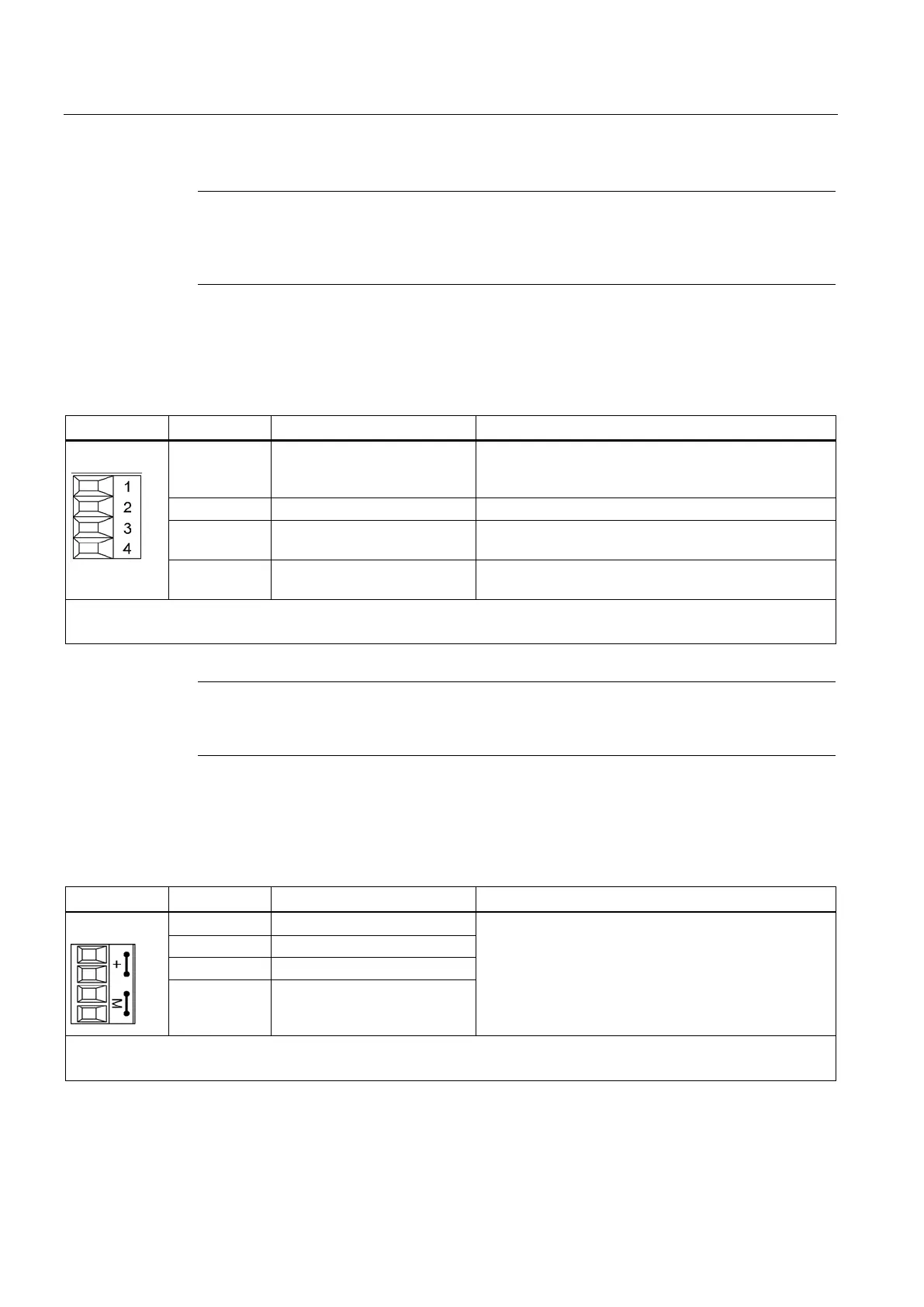
3.9.3.3 X121 temperature sensor and fan control
Table 3- 23 Plug-in screw terminal X121
Terminal Designation Technical data
1 +Temp Output temperature switch
Must be connected to interface X21 of the Active Line
Module.
2 -Temp Temperature switch output
3 +24 V power supply for digital
inputs
Current carrying capacity: 500 mA
4 Disable Fan The fan can be disabled. The fan may be disabled only
while the Active Line Module is disabled.
Type: Screw terminal 1 (Page 755)
Max. connectable cross-section: 1.5 mm
2
Note
If the terminals are not connected (or connected with low level), the fan will run in continuous
mode.
3.9.3.4 X124 Electronics power supply
Table 3- 24 X124 Electronics power supply
Terminal Function Technical data
+ Electronics power supply Voltage: 24 VDC (20.4 ... 28.8 V)
Current
consumption: max. 1.6 A
Max. current via jumper in connector:
20 A at 55° C
+ Electronics power supply
M Electronics ground
M Electronics ground
Type: Screw terminal 2 (Page 755)
Max. connectable cross-section: 2.5 mm
2
Artisan Technology Group - Quality Instrumentation ... Guaranteed | (888) 88-SOURCE | www.artisantg.com

 Loading...


