Motor Modules Booksize Compact
7.3 Interface description
Booksize Power Units
Manual, (GH2), 04/2014, 6SL3097-4AC00-0BP6
495
Note
The total length of the power cables (motor feeder cables and DC link cables) must not
exceed the values listed in Chapter
Combining line reactors and line filters (Page 136).
Note
The motor brake must be connected via connector X11 and X12 on Double Motor Modules.
It is not permitted to directly connect the cable BR
- to the electronics ground M.
Destruction of the motor or motor holding brake as a result of high voltage tolerances of the
motor holding brakes
If the voltage tolerances of the motor holding brakes are not complied with (24 V ± 10 %),
then the brake will malfunction, i.e. the brake will not reliably open. If the motor constantly
runs against the closed brake, the brake or the motor will be destroyed.
• Set the DC power supply to 26 V.
The following general conditions must be satisfied:
• Siemens three-phase motors must be used
• Siemens MOTION-CONNECT power cables must be used
• Motor cable lengths, max. 100 m
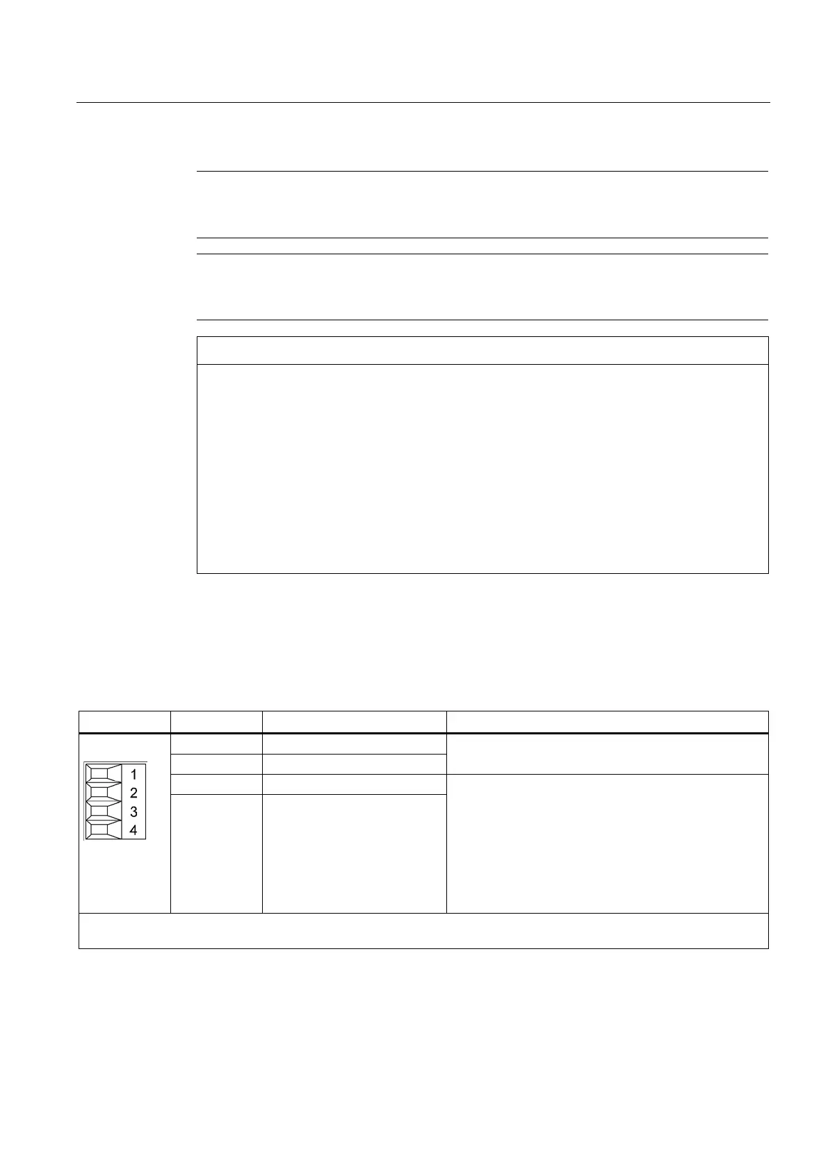
X21/X22 EP terminals/temperature sensor
Table 7- 3 X21/X22 EP terminals / temperature sensor
Temperature sensors: KTY 84-1C130/PTC/bimetallic
switch with NC contact
Supply voltage: 24 V DC (20.4 ... 28.8 V)
Current consumption: 10 mA
Isolated input
Signal propagation times:
L → H: 100 μs
H → L: 1000 μs
The pulse inhibit function is only available when Safety
Integrated Basic Functions are enabled.
4 EP M1 (enable pulses)
Type: Screw terminal 1 (Page 755)
Max. cross-section that can be connected 1.5 mm
2
Artisan Technology Group - Quality Instrumentation ... Guaranteed | (888) 88-SOURCE | www.artisantg.com

 Loading...


