Line Modules Booksize
4.8 Smart Line Modules with internal air cooling
Booksize Power Units
Manual, (GH2), 04/2014, 6SL3097-4AC00-0BP6
283
16 kW to 55 kW Smart Line Modules
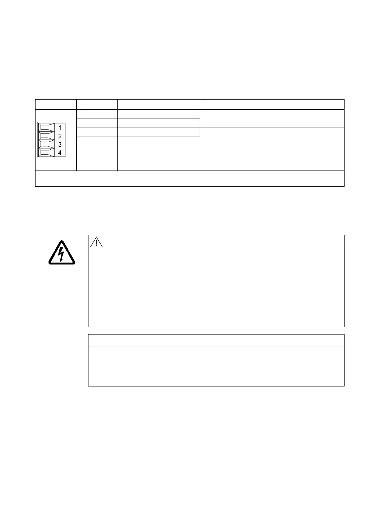
Table 4- 67 X21 EP terminal / temperature sensor for 16 kW to 55 kW Smart Line Modules
Temperature sensors
1)
: KTY 84-1C130/PTC/bimetallic
switch with NC contact
Voltage: 24 V DC
Current consumption: 10 mA
Isolated input
Signal propagation times:
L → H: 100 μs
4 EP M (Enable Pulses)
Type: Screw terminal 1 (Page 755)
Max. cross-section that can be connected 1.5 mm
2
The temperature sensor type and the temperature output can be selected by parameter (see the SINAMICS S120/S150
List Manual).
Temperatures are sensed, but are not evaluated in the Smart Line Module.
Terminals X21.1 and X21.2 - temperature sensor connection
Danger to life due to electric shock in the event of voltage flashovers on the temperature
sensor cable
Voltage flashovers in the signal electronics can occur in motors without safe electrical
separation of the temperature sensors.
• Only use temperature sensors that fully comply with the specifications of the safety
isolation.
• If safe electrical separation cannot be guaranteed (for linear motors or third-party
motors, for example), use a Sensor Module External (SME120 or SME125) or Terminal
Module TM120.
Risk of the motor overheating due to an incorrectly connected KTY temperature sensor
A KTY temperature sensor connected with incorrect polarity cannot detect if the motor
overheats.
• Always connect the KTY sensor with the correct polarity.
Artisan Technology Group - Quality Instrumentation ... Guaranteed | (888) 88-SOURCE | www.artisantg.com

 Loading...


