Motor Modules Booksize
6.2 Motor Modules with internal air cooling
Booksize Power Units
372 Manual, (GH2), 04/2014, 6SL3097-4AC00-0BP6
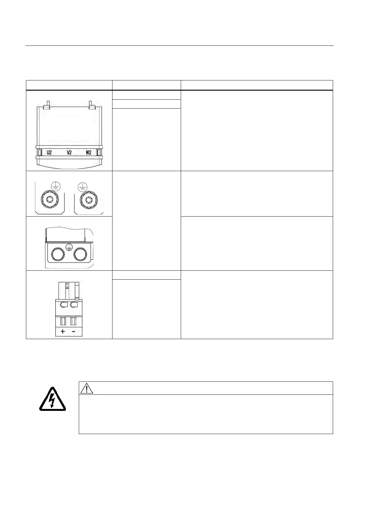
Table 6- 2 X1 motor connection and X11 brake connection for Single Motor Modules 45 A to 200 A
Threaded bolts M6 / 6 Nm
1)
Threaded bolts M8 / 13 Nm
1)
Threaded bolts M8 / 13 Nm
1)
W2
PE connection
Threaded bolts for motor cables: M6 / 6 Nm
1)
Threaded hole for PE: M6 / 6 Nm
1)
Threaded bolts for motor cables: M8 / 13 Nm
1)
Threaded hole for PE: M6 / 6 Nm
1)
Threaded bolts for motor cables: M8 / 13 Nm
1)
Threaded hole for PE: M8 / 13 Nm
1)
2)
:
Voltage: 24 V DC
Max. load current: 2 A
Minimum load current: 0.1 A
Type: Spring-loaded terminal 2 (Page 754)
Max. cross-section that can be connected 2.5 mm
2
:
The brake connector is part of the prefabricated cable.
- (BR-)
For ring cable lugs without insulation
The circuit for protecting the brake against overvoltage is integrated in the Motor Module and does not need to be
installed externally. The max. load current is 2 A, the min. load current 0.1 A.
Danger to life as a result of a hazardous voltage at the 0 V to 48 V DC terminals
Death or serious injury can result when live parts are touched in the event of a fault.
• Only connect protective extra-low voltages (PELV / SELV) to all connections and
terminals between 0 to 48 V DC.
Artisan Technology Group - Quality Instrumentation ... Guaranteed | (888) 88-SOURCE | www.artisantg.com

 Loading...


