Motor Modules Booksize
6.4 Motor Modules with cold plate
Booksize Power Units
Manual, (GH2), 04/2014, 6SL3097-4AC00-0BP6
443
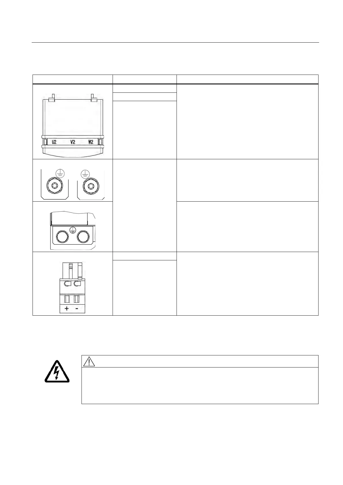
Table 6- 33 X1 motor connection and X11 brake connection for Single Motor Modules 45 A to 200 A
Threaded bolts M6 / 6 Nm
1)
Threaded bolts M8 / 13 Nm
1)
Threaded bolts M8 / 13 Nm
1)
W2
PE connection
Threaded bolts for motor cables: M6 / 6 Nm
1)
Threaded hole for PE: M6 / 6 Nm
1)
Threaded bolts for motor cables: M8 / 13 Nm
1)
Threaded hole for PE: M6 / 6 Nm
1)
Threaded bolts for motor cables: M8 / 13 Nm
1)
Threaded hole for PE: M8 / 13 Nm
1)
2)
:
Voltage: 24 V DC
Max. load current: 2 A
Minimum load current: 0.1 A
Type: Spring-loaded terminal 2 (Page 754)
Max. cross-section that can be connected 2.5 mm
2
:
The brake connector is part of the prefabricated cable.
- (BR-)
For ring cable lugs without insulation
)
The circuit for protecting the brake against overvoltage is integrated in the Motor Module and does not need to be
installed externally. The max. load current is 2 A, the min. load current 0.1 A.
Danger to life as a result of a hazardous voltage at the 0 V to 48 V DC terminals
Death or serious injury can result when live parts are touched in the event of a fault.
• Only connect protective extra-low voltages (PELV / SELV) to all connections and
terminals between 0 to 48 V DC.
Artisan Technology Group - Quality Instrumentation ... Guaranteed | (888) 88-SOURCE | www.artisantg.com

 Loading...


