UMSITRPDS3-1 Calibration And Maintenance
November 2005
7-15
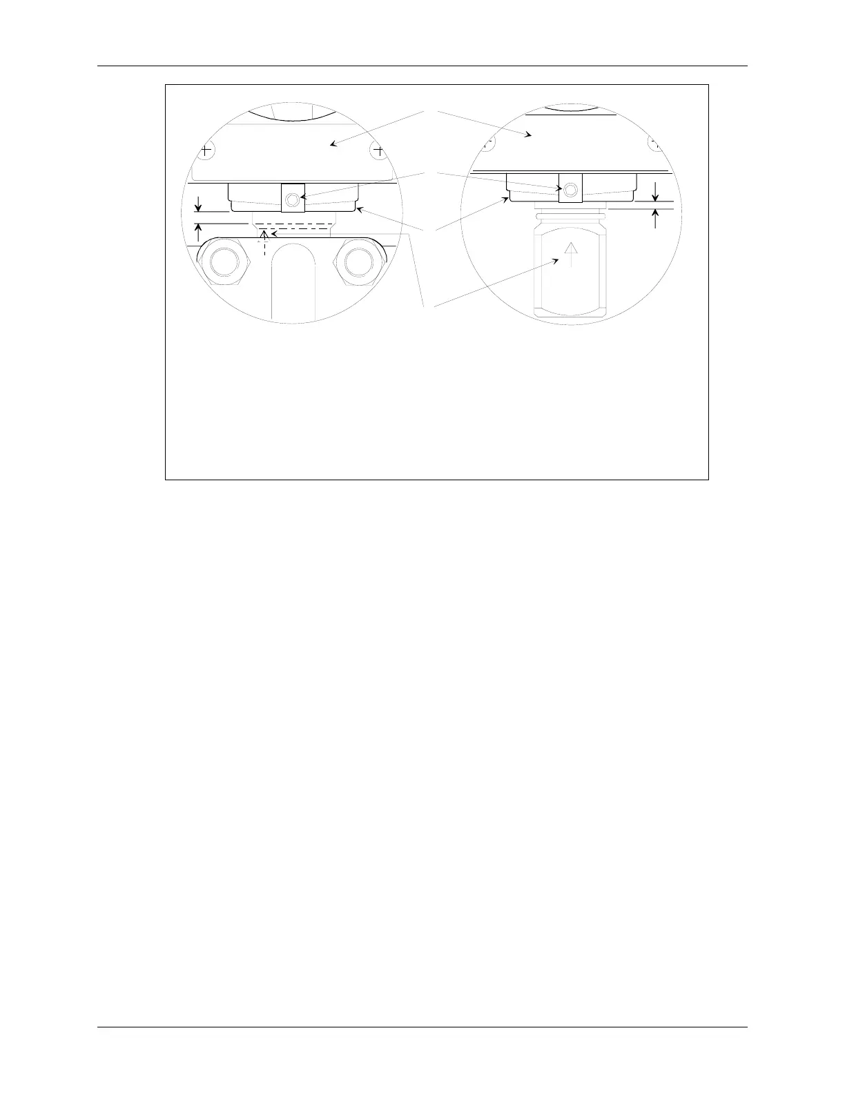
MG00353a
Differential Construction
Gauge Construction
1
2
3
4
Dimension A = 0.1" +/- 0.03 (2.6 mm +/- 0.75)
A
A
1
2
3
4
Enclosure rotation arrow (enclosure rotation reference point)
Ramp-shaped recessed area indicating enclosure rotation range
Enclosure setscrew, use 3/32 (2.5 mm) Allen screw
Tag plate
FIGURE 7-4 Measuring Cell Alignment and Insertion Depth
6. Tighten the enclosure setscrew to 30.1 to 30.9 in lbs (3.4 to 3.6 Nm).
7. Get the electronics module and connect the measuring cell board as described in Section 7.4.2.
8. Install the electronics module as described in Section 7.4.2.
9. Install the display as described in Section 7.4.1.
10. Install the end cap by turning it clockwise until the O-ring contacts the enclosure. Turn the cap one
additional turn to compress the O-ring.
11. Apply power to the transmitter; see Section 3 for wiring diagrams. Refer to the table in Section 7.4
and to Section 6 On-Line Configuration and Operation and configure the transmitter.
12. Reinstall transmitter as described in Section 7.6 Transmitter Replacement.
 Loading...


