Model Designations and Specifications UMSITRPDS3-1
November 2005
9-14
Flanged Level Transmitter Accessories
Order number
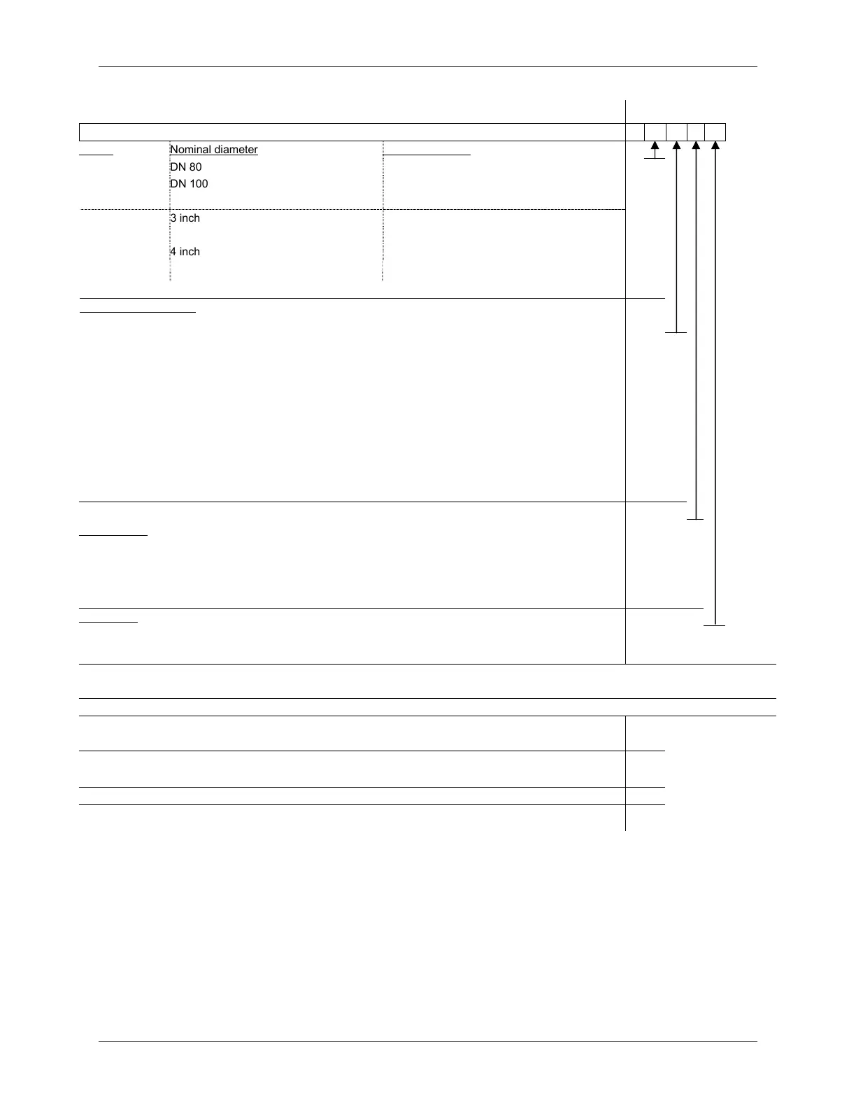
Mounting flange, mounted directly on transmitter, two-wire, 7MF4912-
3
Flange Nominal diameter Nominal pressure
Connection per DN 80 PN 40 psi
D
DIN 2501 DN 100 PN 16 psi
G
PN 40 psi
H
Connection per 3 inch 150 lb/sq. in.
Q
ANSI B 16.5 300 lb/sq. in.
R
4 inch 150 lb/sq. in.
T
300 lb/sq. in.
U
Special version according to customer specifications
Z J1Y
Material of wetted parts
Stainless steel M.-No. 1.4571:
Without foil, uncoated
A
With PTFE foil
1)
E
With ECTFE coating
1)
F
With PFA coating
1)
D
Monel 400, W.-No. 2.4360
G
Hastelloy B2, W.-No. 2.4617
H
Hastelloy C276, W.-No. 2.4819
J
Tantalum
K
Hastelloy C4, W.-No. 2.4610
U
Special version to customer specifications
Z K1Y
Smooth processing face according to DIN 2526, Form D:
Tube length
2)
Flush mount
0
2” / 50 mm
1
4” / 100 mm
2
6” / 150 mm
3
8” / 200 mm
4
Filling liquid
Silicone oil M5
1
Special version to customer specifications
9 M1Y
Other versions for mounting flange
Add "-Z" to the order number and add short spec.
7MF4912 - . . . . . -Z
With flame barrier for mounting in zone 0 (with documentation)
A01
Manufacturer test certificate M acc. to DIN 55 350, Part 18, and ISO 8402 (not with supplement "P01")
C11
Acceptance test certificate B according to DIN 50 049; see Section 3.1 and EN 10 204
C12
Vacuum-proof version (use in vacuum pressure range)
V04
Calculation of span of the corresponding transmitter, enclose completed questionnaire! (Not with supplement
“P01.”)
Y05
Notes:
1)
For vacuum on request
2)
Prices for the stated tube lengths are based on the material of the wetted part: stainless steel M. No. 1.4571.
Prices for other materials are available upon request.
 Loading...


