Online Configuration Map for
Siemens SITRANS P DSIII Pressure Transmitter with
Model 375 Field Communicator
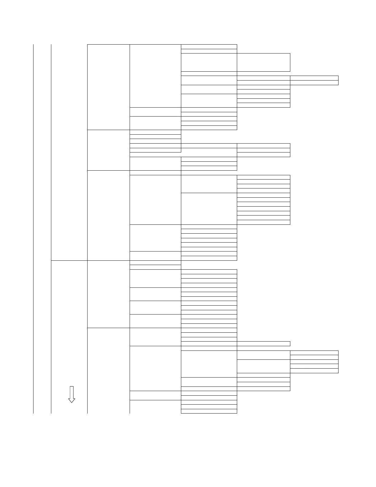
5 Config inp/outp, 3 Output 1 Analog output 1 Analog output +
Continued 2 Percent range +
3 Pres xfer function Linear
Sq Rt, lin to Strtpt
Sq Rt, 4 mA to Strtpt
Sq Rt, 2 steps lin to Startpt
NA/4 Startpoint square root
4/5 Zero and Span 1 Zero/Span set 1 Out Scaling PV >1
2 Apply values >2
5/6 Current Limits 1 Lower AO Limit
2 Upper AO Limit
6/7 Alarms 1 AO Alarm Type
2 Alarm LRV
3 Alarm URV
2 Sensor trim points 1 Lower sensor trim point
2 Upper sensor trim point
3 HART output 1 Polling address
2 Num request preambles
3 Num response preambles
4 Local meter 1 Meter type
2 Unit tracking
3 Local Display unit
4 LCD Settings 1 LCD Scaling, if On: 2 LCD Unit
5 Bargraph 3 LCD LRV
4 LCD URV
6 Access Control 1 Local keys control mode
2 Write protect
3 Set write protect --> M
5 Mech. Construction 1 No of electronic changes
Mech = mechanical 2 Design 1 Sensor 1 Fill fluid
2 Isolation material (diaphr)
3 O ring material
4 Module range
2 Remote Seal 1 Number remote seal (RS)
2 RS type
3 RS isolator material
4 RS fill fluid
5 Extension length
6 Extension type
7 Capillary length
3 Process Connection 1 Process Connection
2 DrainVent / plug mat
3 DrainVent / plug pos
4 Process flange bolt
5 Flange type
6 Flange material
4 Electronic Connection 1 Electr housing material
2 Electr connection
6 Diagnosis/Service 1 Status 1 Status summary
2 Extended device status
3 Hardw/Firmw status 1 RAM failure
2 ROM failure OFF = OK
3 Electronic EEPROM ON = Problem
# List continues
4 Diag Alarm Status 1 Calibration Alarm
2 Service Alarm
# List continues
5 Diag Warn Status 1 Calibration Warning
2 Service warning
# List continues
6 Simulation status 1 Pressure simulation
2 El simulation
3 Sensor temp simulation
2 Device 1 Selftest/Reset 1 Selftest --> M
2 Display Test --> M
3 Master reset --> M
4 Changes Config 1 Config changed counter
2 Sensor trim 1 Restore mfgr trims --> M mfgr = manufacturer
2 Sensor trim 1 Sensor trim points 1 Lower sensor trim point
2 Upper sensor trim point
2 Sensor trim 1 Pres zero trim--> M
2 Lower sensor trim --> M
3 Upper sensor trim --> M
3 Trimpoint summary
3 Trim analog output 1 D/A trim --> M
Continued on pg 4 2 Scaled D/A trim --> M
4 Position correction 1 Position corr --> M
3 Simulation/Test 1 Loop test --> M Simulation AO
2 Inputs --> M Simulation Fixed / Ramp
4 Access Control 1 Local keys control mode
2 Write protect
3 Set write protect --> M
Page 3
 Loading...


