Connection of the Components
5.3 Line Modules Interfaces Description
Guide for the SINUMERIK 840D sl machine configuring
5-20 Manual, 07/2006 Edition, 6FC5397-6CP10-0BA0
Warning
For operation, ground must be attached to the -X21:3 24 VDC terminals and the -X21:4
terminals. For cancelation, a pulse suppression will be activated. Feedback is deactivated
and the bypass relay drops out. If the Line Module is not separated from the supply system
when the EP terminal is opened (e.g. no main power switch present), the DC link will remain
charged.
Notice
If the main power switch is used to switch off a running drive group, the voltage at terminal 3
(EP +24 V) and 4 (EP M) must be interrupted beforehand. This can be achieved, for
example, with a leading (≥10 ms) disconnecting auxiliary contact.
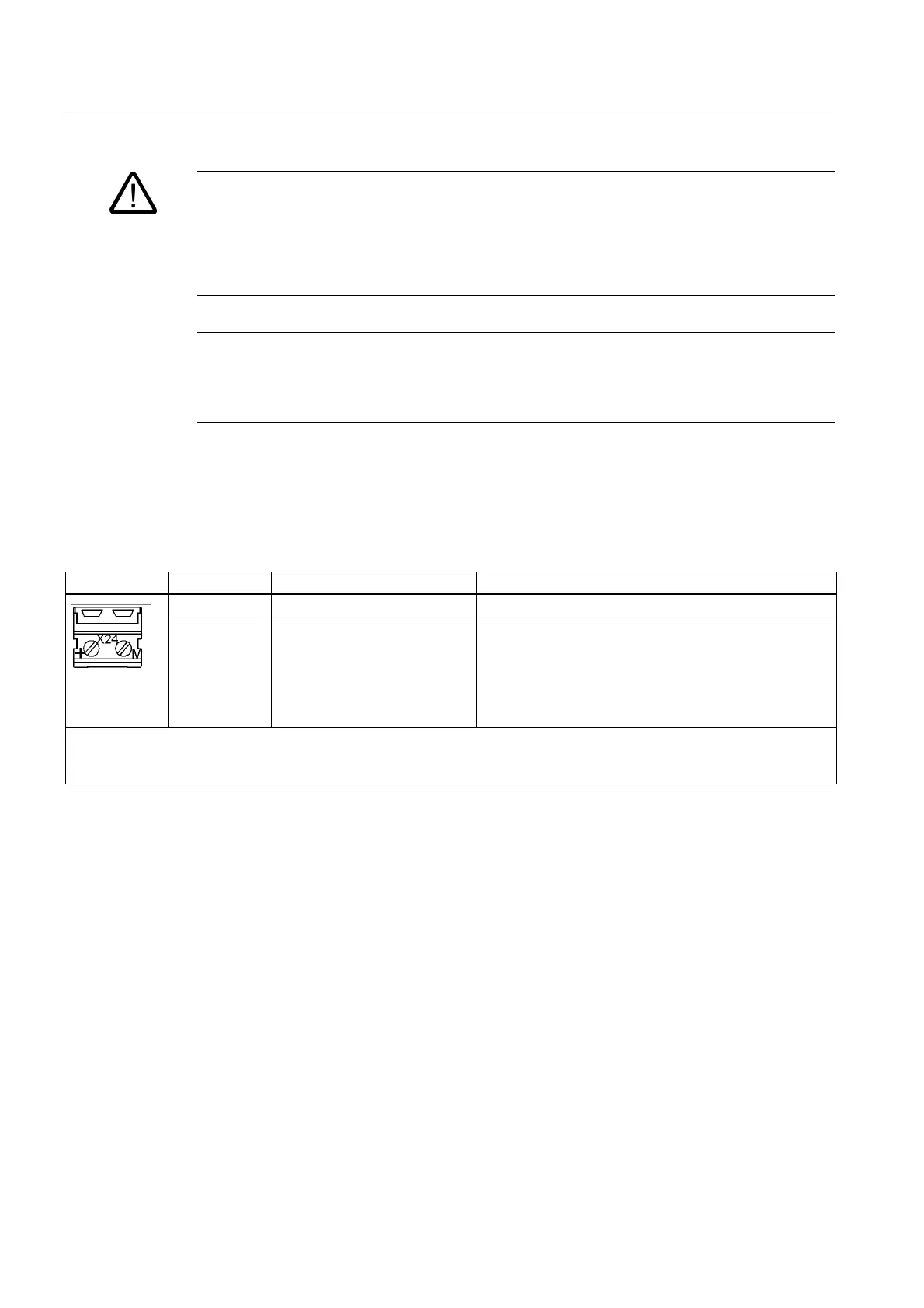
5.3.2.5 Active Line Module X24 24 V Terminal Adapter
Table 5-4 X24 terminal block
Terminal Designation Technical data
+ 24 V supply 24 VDC supply voltage
M Chassis ground Electronics ground
(tolerance limit 20.4 VDC to 28.8 VDC, voltage
interruption for 3 ms without function impairment).
Used for the central infeed of the 24 VDC power supply
of the drive group
The 24 V terminal adapter is supplied as standard
Max. connectable cross-section: 6 mm
2
Type: Screw terminal 5
 Loading...


