Structure of the drive group
2.6 Heat Dissipation of the Control Cabinet
Guide for the SINUMERIK 840D sl machine configuring
2-36 Manual, 07/2006 Edition, 6FC5397-6CP10-0BA0
2.6.6 Dimensioning Climate Control Equipment
Cabinet manufacturers provide calculation programs for selecting climate control equipment.
It is always necessary to know the power loss of the components and equipment installed in
the cabinet.
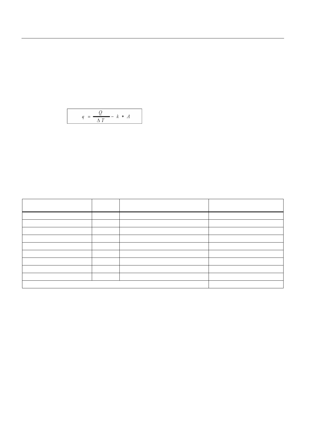
The physical relationship is shown in the following example.
Figure 2-27 Formula to calculate the power loss
q = thermal power that has to be dissipated through a cooling unit [W / K]
Q = power loss [W]
∆T = temperature difference between the room and cabinet interior [K]
k = thermal resistance value, e.g. sheet-steel, painted 5.5 [W / (m
2
* K)]
A = free-standing cabinet surface area [m
2
]
Table 2-7 Example, calculating the power loss of a drive configuration
Component Number Total power loss [W]
(including electronic losses)
Total power loss [W]
CU320 1 20 20
Line filters 1 90 90
Line reactor 1 250 250
Active line module 36 kW 1 666 666
Motor module 18 A 2 185,4 370,8
Motor module 30 A 3 311,6 934,8
SMC 5 10 50
SITOP 20 1 53 53
Line Contactor 1 12 12
Total: 2446,6
Assumption:
Free-standing cabinet surface area A = 5 m
2
Temperature difference between the room and cabinet interior ∆T = 10 K
q = (2415 [W] / 10 [Κ]) - 5.5 [W / (m
2
* K)] * 5 [m
2
] = 214 [W/K]
 Loading...


