Connection of the Components
5.9 Motor Connection
Guide for the SINUMERIK 840D sl machine configuring
5-66 Manual, 07/2006 Edition, 6FC5397-6CP10-0BA0
;;
'&1
'&3
'&1
'&3
8
9
%5
:
%5
;
a
0
(
;
5($'<
'&/,1.
/('V
7HPS
;
7HPS
(30
(39
;
˽
˽
0RWRU0RGXOH
0
0
9MXPSHU
)DQ
'5,9(&/L4VRFNHW
'5,9(&/L4VRFNHW
'5,9(&/L4VRFNHW
5HTXLUHGIRU6DIHW\
,QDGGLWLRQIRU0RWRU0RGXOHV$WR$
&RQWDFWWKURXJKWKHVKLHOGSODWH
9WRWKHQH[WPRGXOH
8
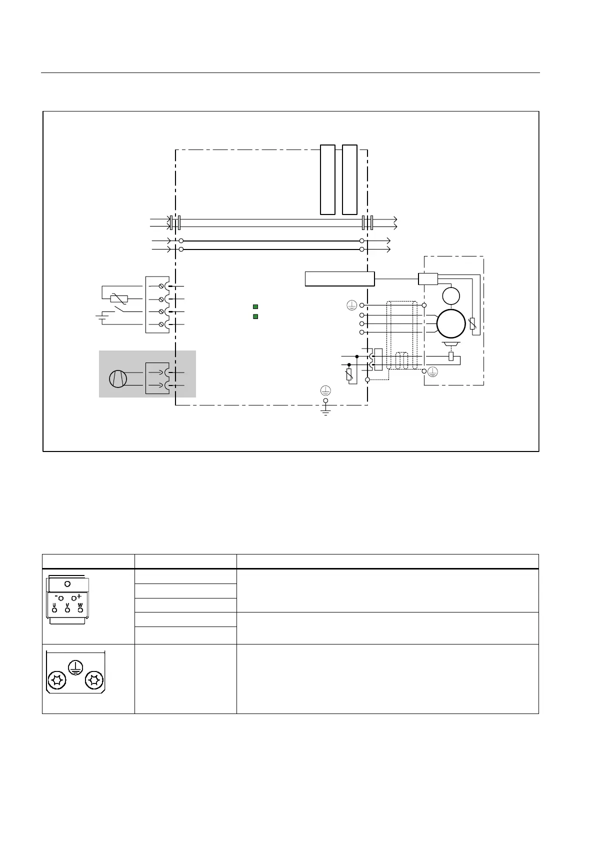
Figure 5-30 Example connection of Single Motor Modules 45 A to 200 A
5.9.3 Motor/brake connection
Table 5-25 Terminal block X1/X2 Motor Modules 3 A to 30 A and Double Motor Modules 3 A to 18 A
Terminal Technical specifications
U (U2)
V (V2)
W (W2)
Motor connection
+ (BR+)
- (BR-)
Brake connection
PE connection Threaded hole M5/3 Nm
1
1
for ring cable lugs to DIN 46234
 Loading...


