Connection of the Components
5.11 Brake Connection
Guide for the SINUMERIK 840D sl machine configuring
5-76 Manual, 07/2006 Edition, 6FC5397-6CP10-0BA0
5.11.3 Connection of the Brake using Interface Relay
The motor holding brake can be attached directly to the provided connecting terminal or
indirectly using an interface relay switched between. This may be necessary, for example,
when the brake rated current I
BR
> DC 2 A or the connection voltage of the brake is 1AC
230 V. It is important, however, that the rated current of the interface relay is > 100 mA to
prevent a fault message from the brake monitoring.
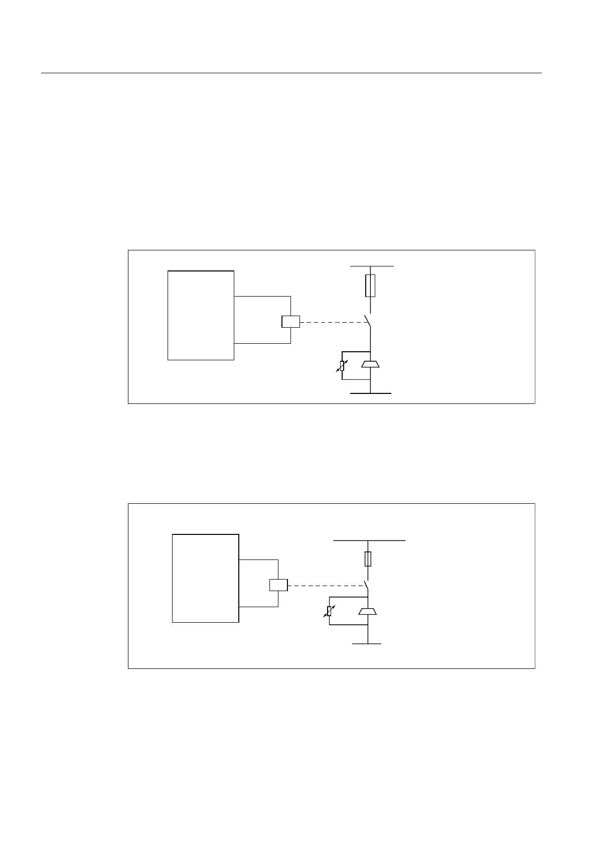
Brake current IBR > 2 A DC
0RWRU
0RGXOH
%5
.
)
/
/
%5
5 4
'&9
Figure 5-36 Brake current IBR > 2 A DC
Protective circuit for the interface relay is not required because this function exists in the
Motor Module. A protective circuit, however, must be provided for the brake.
Supply voltage not 24 VDC.
%5
.
%5
)
1
$&9+]
0RWRU
0RGXOH
4
5
/
Figure 5-37 Supply voltage not 24 VDC.
Protective circuit of the brake coil required. For the choice of the protective circuit, ensure
that the demagnetization of the brake is achieved fast. This is performed, for example, with
varistors for an AC supply power (also refer to the motors configuring guide).
 Loading...


