Connection of the Components
5.3 Line Modules Interfaces Description
Guide for the SINUMERIK 840D sl machine configuring
5-22 Manual, 07/2006 Edition, 6FC5397-6CP10-0BA0
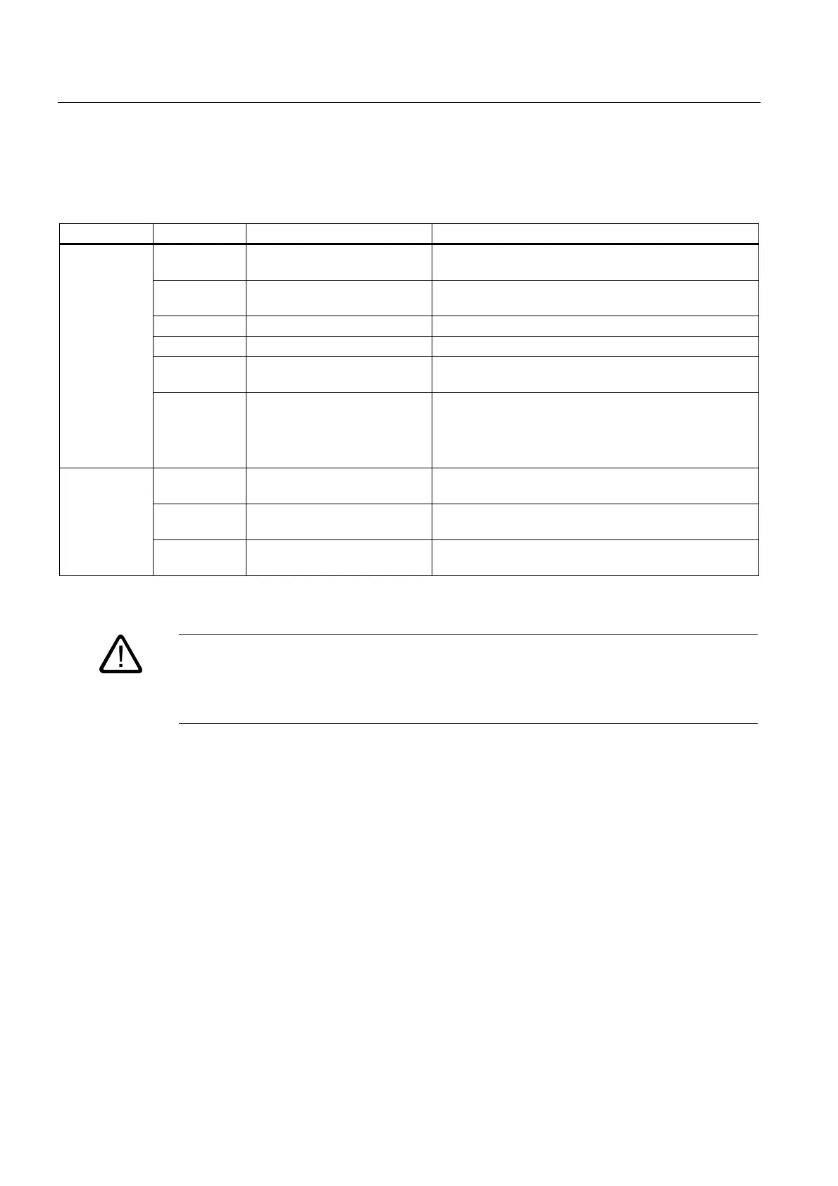
5.3.2.9 Meaning of the LEDs on the Active Line Module
Table 5-6 Meaning of the LEDs on the Line Module
LED Color State Description
- Off Electronics power supply outside the permissible
tolerance range.
Green Steady light The component is ready for operation and cyclic DRIVE-
CLiQ communication is taking place.
Orange Steady light DRIVE-CLiQ communication is being established.
Red Steady light At least one fault is present in this component.
Green
Red
Flashing
2 Hz
Firmware is being downloaded.
READY
Green/
Orange
or
Red/ Orange
Flashing
2 Hz
Component recognition via LED is activated (p0124).
Note:
Both options depend on the LED status when module
recognition is activated via p0124 = 1.
- Off Electronics power supply outside the permissible
tolerance range.
Orange Steady light DC link voltage within permissible tolerance range (only
when ready for operation)
DC LINK
Red Steady light DC link voltage outside the permissible tolerance range
(only when Active Line Module is ready for operation).
Warning
Hazardous DC link voltages may be present at any time regardless of the status of the "DC
link" LED.
The warning information on the components must be carefully observed!
Cause and rectification of faults
The following reference contains information about the cause and rectification of faults:
Reference: /IH1/ SINAMICS S120, Commissioning Manual.
 Loading...


