Connection of the Components
5.4 Motor Modules Interface Description
Guide for the SINUMERIK 840D sl machine configuring
5-36 Manual, 07/2006 Edition, 6FC5397-6CP10-0BA0
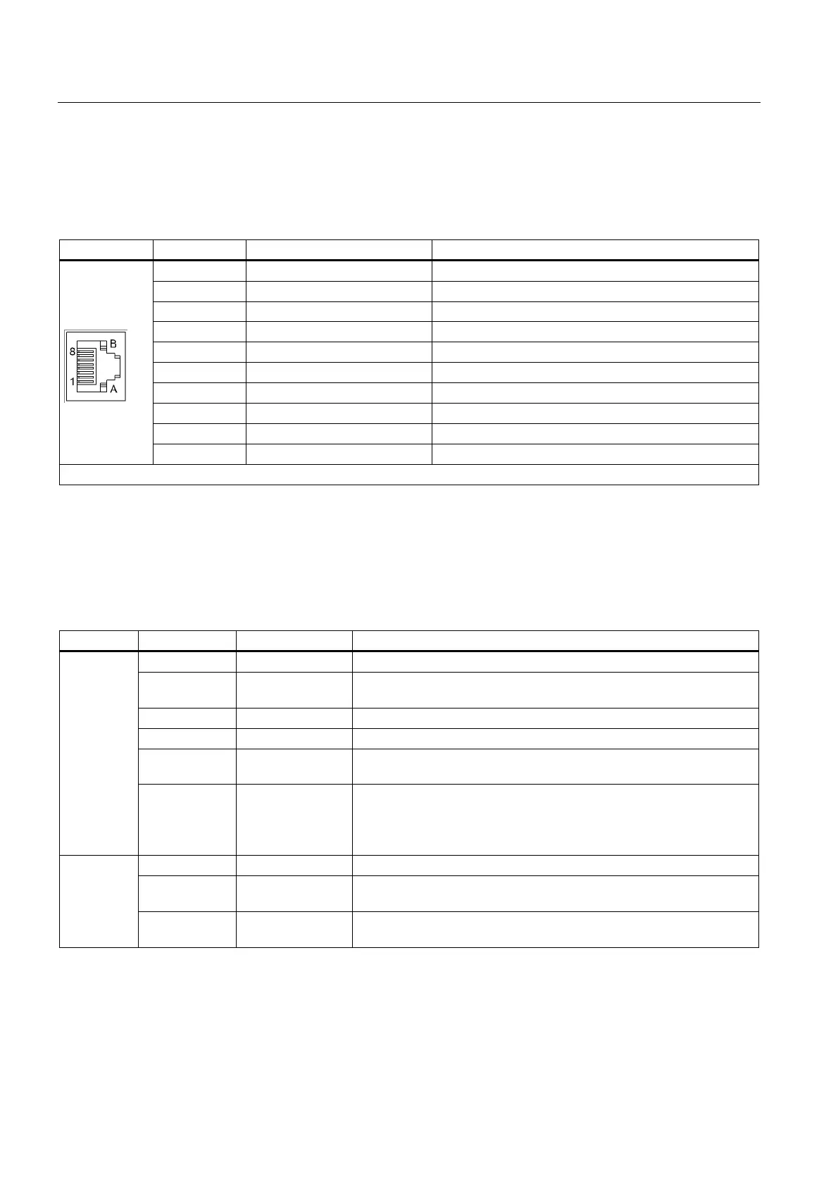
5.4.5 X200-X203 DRIVE-CLiQ interface
Table 5-15 DRIVE-CLiQ interface X200-X202: Single Motor Module
DRIVE-CLiQ interface X200-X203: Double Motor Module
Pin Name Technical specifications
1 TXP Transmit data +
2 TXN Transmit data -
3 RXP Receive data +
4 Reserved, do not use
5 Reserved, do not use
6 RXN Receive data -
7 Reserved, do not use
8 Reserved, do not use
A + (24 V) Power supply
B GND (0 V) Electronic ground
Blanking plate for DRIVE-CLiQ interface: Molex, order number: 85999-3255
5.4.6 Meaning of the LEDs on the Motor Module
Table 5-16 Meaning of the LEDs on the Motor Module
LED Color State Description
- Off Electronics power supply outside the permissible tolerance range.
Green Steady light The component is ready for operation and cyclic DRIVE-CLiQ
communication is taking place.
Orange Steady light DRIVE-CLiQ communication is being established.
Red Steady light At least one fault is present in this component.
Green
Red
Flashing
2 Hz
Firmware is being downloaded.
READY
Green/ Orange
or Red/Orange
Flashing
2 Hz
Component recognition via LED is activated (p0124).
Note:
Both options depend on the LED status when module recognition is
activated via p0124 = 1.
- Off Electronics power supply outside the permissible tolerance range.
Orange Steady light DC link voltage within permissible tolerance range (only when ready
for operation)
DC LINK
Red Steady light DC link voltage outside permissible tolerance range (only when ready
for operation)
 Loading...


