Structure of the drive group
2.6 Heat Dissipation of the Control Cabinet
Guide for the SINUMERIK 840D sl machine configuring
Manual, 07/2006 Edition, 6FC5397-6CP10-0BA0
2-23
2.6 2.6 Heat Dissipation of the Control Cabinet
2.6.1 Ventilation Clearances of the SINUMERIK Components
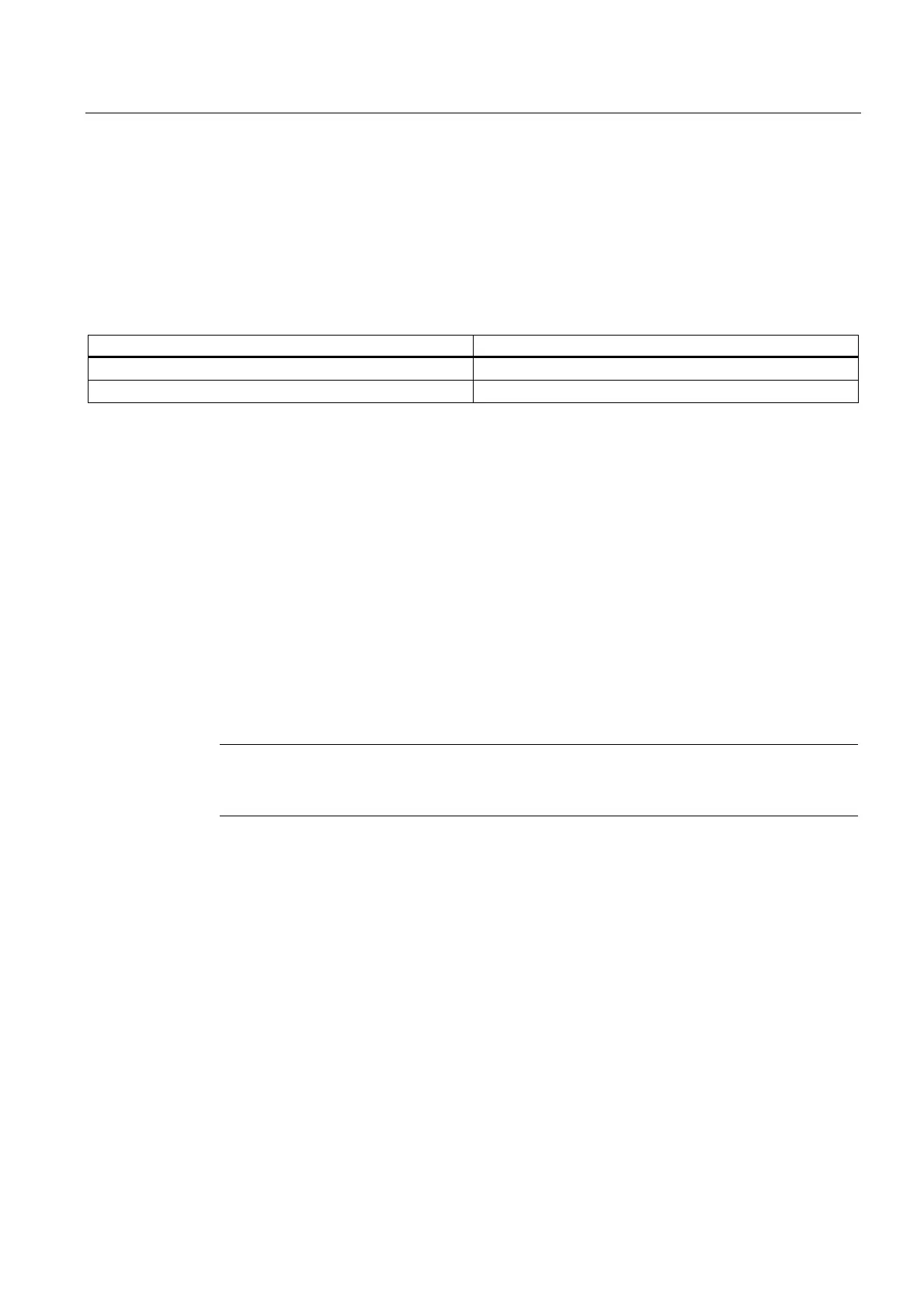
Table 2-1 Ventilation clearances above and below the components
Component Clearance [mm]
NCU 7x0 80 mm
NX1x 80 mm
2.6.2 General
The cabinet can be cooled, among others, by using:
● filtered fans
● heat exchangers or
● cooling units.
The decision in favor of one of these methods will depend on the prevailing ambient
conditions and the cooling power required.
The air routing inside the control cabinet and the cooling clearances specified here, must be
carefully observed. No other components or cables must be located in these areas.
Caution
If you do not observe the guidelines for installing SINAMICS equipment in the cabinet, this
can reduce the service life of the equipment and result in premature component failure.
You must take into account the following specifications when installing a SINAMICS drive
line-up:
● Ventilation clearance
● Cable routing
● Air guidance, air-conditioner
 Loading...


