Connection of the Components
5.7 Control Supply Module (CSM)
Guide for the SINUMERIK 840D sl machine configuring
5-58 Manual, 07/2006 Edition, 6FC5397-6CP10-0BA0
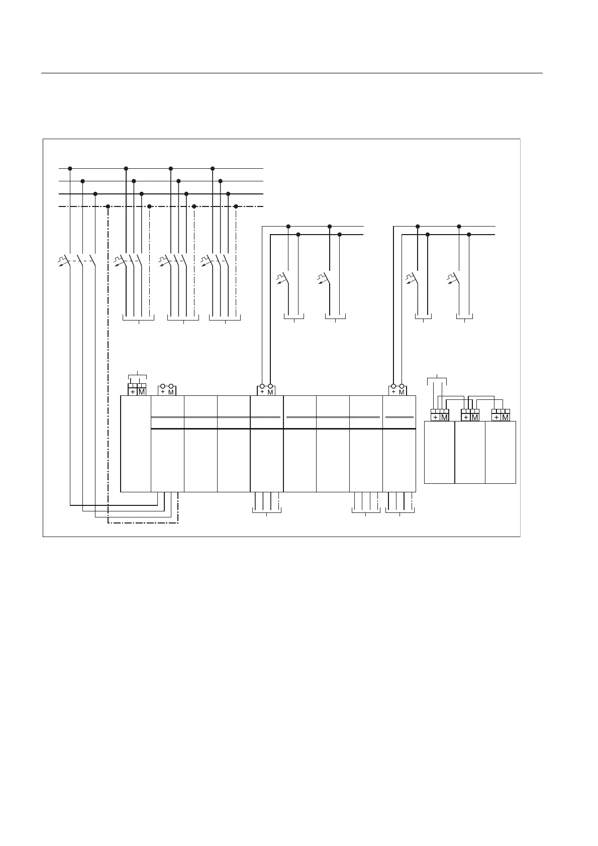
5.7.4 Control Supply Module Power Supply - Connection Example
;
1&8
[
;
60&
;
60&
;
60&
$FWLYH
/LQH
0RGXOH
9'&
0RWRU
0RGXOH
&60
9'&
0RWRU
0RGXOH
&60
9'&
&RQWURO
6XSSO\
0RGXOH
9'&
&RQWURO
6XSSO\
0RGXOH
9'&
&RQWURO
6XSSO\
0RGXOH
9'&
0RWRU
0RGXOH
&60
9'&
0RWRU
0RGXOH
&60
9'&
&60
&60
1&8
&60 &60
60&
/
/
/
3,
$&3(9+]
1&8
60&
9'& /
0
9DOYHV &RQWDFWRUV
9'& /
0
&60 &60
!
! ! ! !
4 4 4 4
!
!
!
!
!
!
!
!
! !!
!!!
!
!
!
!
!
!
) ) ) )
!
'&/'&/ '&/ '&/ '&/ '&/'&/'&/
Figure 5-23 CSM power supply connection example
1. Protection using the manufacturer's specifications
2. Max. connection cross-section 2.5 mm
2
, max. fuse 20 A
3. Max. connection cross-section 6 mm
2
, max. fuse 20 A
4. The selection of the protection depends on the total current of the connected consumers.
5. The cross-section depends on the selected protection and on the required current.
6. The current carrying capacity of the 24 VDC busbar is max. 20 A; if this value is
exceeded, the 24 V busbar must be interrupted and an additional supply selected.
7. The 24 VDC terminal adapters are included with the supplied Line Module. If additional
terminal adapters are required, they must be ordered separately (6SI3162-2AA00-0AA0).
8. Observe the maximum current carrying capacity of the DC link busbar on the Control
Supply Module (100 A) when the drive group is formed; also refer to the "Current
Carrying Capacity of the DC Link Busbar" section.
 Loading...


