Structure of the drive group
2.3 Current Carrying Capacity of the DC Link Busbar
Guide for the SINUMERIK 840D sl machine configuring
Manual, 07/2006 Edition, 6FC5397-6CP10-0BA0
2-11
2.3 2.3 Current Carrying Capacity of the DC Link Busbar
The current carrying capacity of the DC link busbar must be observed for the configuring and
the construction of the drive group.
The maximum current carrying capacity of the DC link busbar differs depending on the width
of the power units.
● For power units from 3 A to 60 A (max. width 150 mm) and DC link components (Braking,
Capacitor and Control Supply Module), the DC link busbar can be loaded with 100 A.
● For power units from 85 A to 200 A (200 / 300 mm width), the DC link busbar can be
loaded with 200 A.
If the current carrying capacity of the DC link busbar is exceeded, two solutions are possible:
either the building of the drive group with infeed from left and right (center infeed; see below)
or the use of another Line Module.
Note
The following examples are based on the concurrent use and loading of the Motor Modules
with the rated output current of the Motor Modules. The current values are taken from the
Equipment Manual for Booksize Power Units or the NC61 catalog.
Example 1:
Connection of several Motor Modules with different current carrying capacity of the DC link
busbar to a Line Module.
$$$$
$
/LQH
0RGXOH
N:
0RWRU
0RGXOH
$
0RWRU
0RGXOH
$
0RWRU
0RGXOH
$
0RWRU
0RGXOH
$
$$$$
$$$$
$$
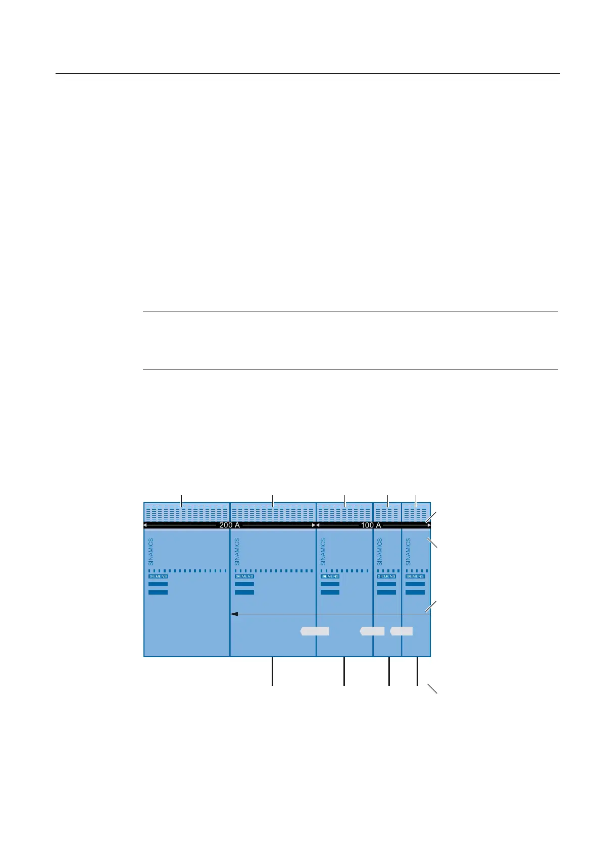
&XUUHQWFDUU\LQJFDSDFLW\RI
WKH'&OLQNEXVEDU
/RDGLQJRIWKH'&OLQNEXVEDU
'&OLQNFXUUHQW,
'
IRUUDWHG
RXWSXWFXUUHQW,
1
IRUWKH0RWRU
0RGXOH
,QFUHDVHRIWKHORDGLQJRI
WKH'&OLQNEXVEDU
0RWRUFXUUHQW UDWHGRXWSXW
FXUUHQW,
1
0RWRU0RGXOH
Figure 2-9 Regular construction; DC link busbars not overloaded
 Loading...


