Connection of the Components
5.3 Line Modules Interfaces Description
Guide for the SINUMERIK 840D sl machine configuring
Manual, 07/2006 Edition, 6FC5397-6CP10-0BA0
5-29
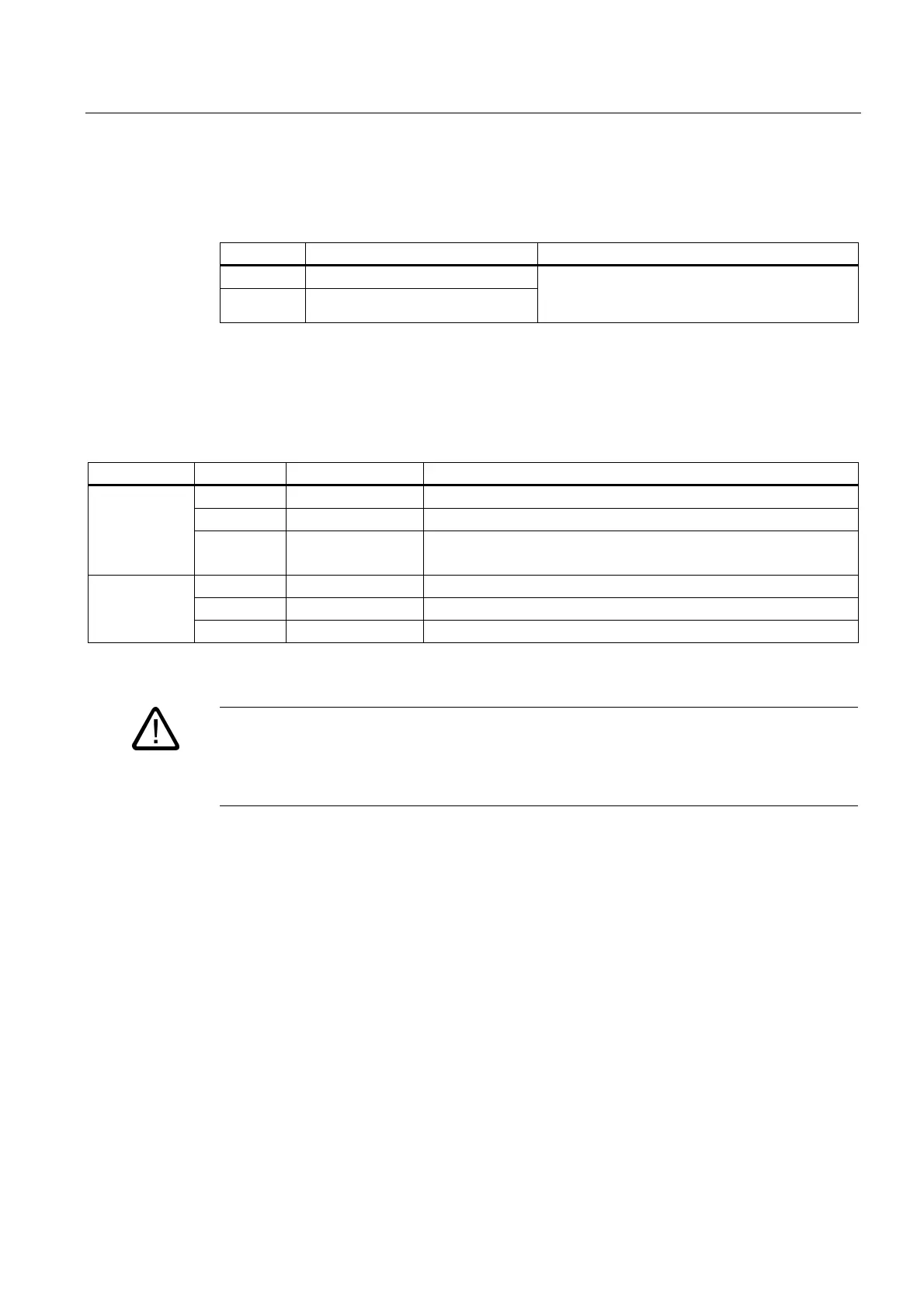
5.3.3.8 Smart Line Module DC Link Busbar
Busbar Designation Remark
DCP DC link plus pole
DCN DC link minus pole
Two connection straps on the distribution busbar
can be used to pass the voltage potential to
neighboring components.
5.3.3.9 Meaning of the LEDs on the Smart Line Module
Table 5-11 Meaning of the LEDs on the Smart Line Module
LED Color State Description
Green Steady light Operation
Yellow Steady light Pre-charging not yet complete; bypass relay dropped out
READY
Red Steady light Overtemperature/overcurrent switch-off, or
Electronics power supply outside the permissible tolerance range
OFF Electronics power supply outside the permissible tolerance range
Yellow Steady light DC link voltage within permissible tolerance range
DC LINK
Red Steady light DC link voltage outside permissible tolerance range
Warning
Hazardous DC link voltages may be present at any time regardless of the status of the "DC
link" LED.
The warning information on the components must be carefully observed!
Cause and rectification of faults
The following reference contains information about the cause and rectification of faults:
Reference: /IH1/ SINAMICS S120 Commissioning Manual
 Loading...


