Connection of the Components
5.8 Cable Lengths
Guide for the SINUMERIK 840D sl machine configuring
5-62 Manual, 07/2006 Edition, 6FC5397-6CP10-0BA0
5.8.3 Equipotential bonding
The SINAMICS S120 Booksize drive system is designed for use in control cabinets with
protective conductor terminal.
If the drive line-up is arranged on a common unpainted metal-surfaced mounting plate, e.g.
with a galvanized surface, no additional equipotential bonding is needed within the drive line-
up as
● All parts of the switchgear assembly are connected to the protective conductor system.
● The mounting plate is connected with the external PE conductor by means of a finely-
stranded copper conductor with a cross-section of 16 mm², including the outer conductor.
From a cross-section of 25 mm² copper, the outer cross-section of the finely-stranded
conductor is halved.
For other installation methods, equipotential bonding must be implemented using conductor
cross-sections as stated in the second item in the list or at least equal to the conductance.
If components are mounted on DIN rails, the data listed in the second item applies for
equipotential bonding. If only smaller connection cross-sections are permitted on the
components, use the largest possible, e.g. 6 mm
2
for SMC. These requirements also apply
to distributed components located outside the cabinet.
For a PROFIBUS connection between two control cabinets, a fine-wire potential equalizing
conductor with a cross-section of 4 mm
2
should be used. This conductor must be laid
together with the PROFIBUS connection cable and connected to the NCU 7x0 using a cable
lug.
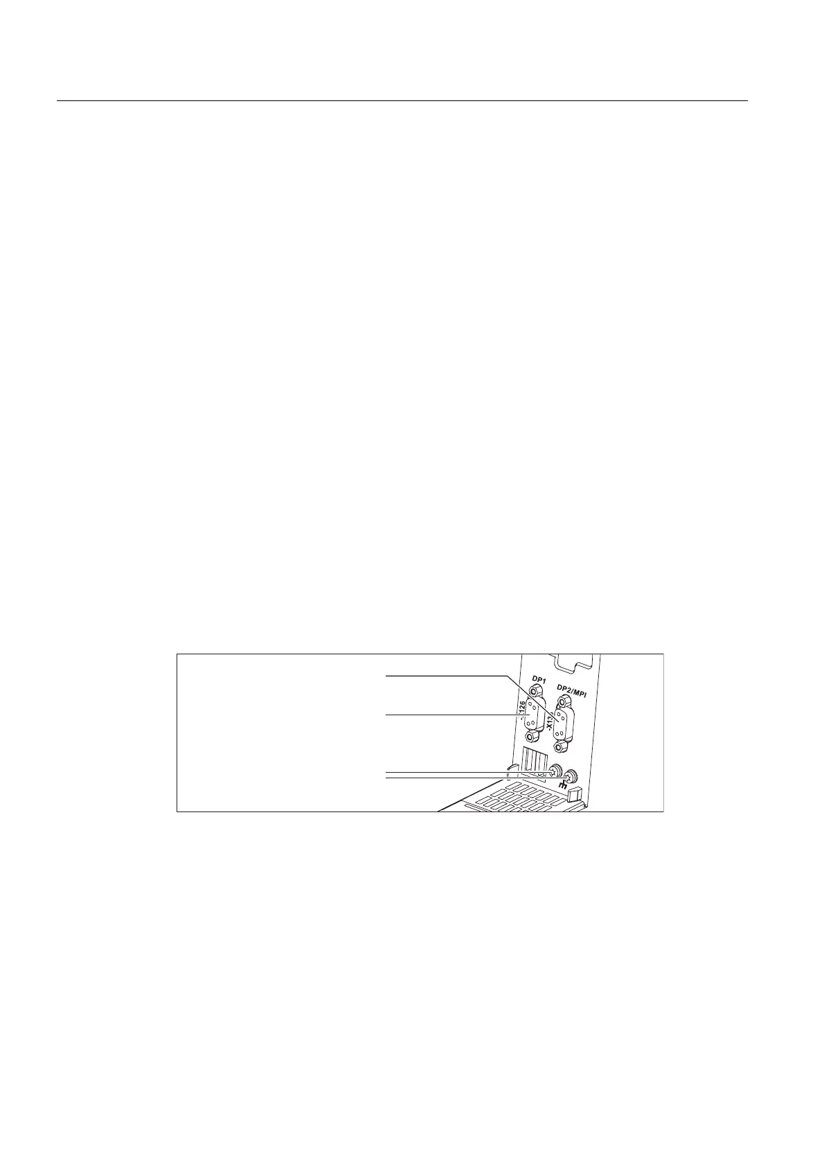
Equipotential bonding and shielding for PROFIBUS
The cable shield must be connected over a large contact surface area.
352),%86;FRQQHFWLRQ
(TXLSRWHQWLDOERQGLQJFRQQHFWLRQV
DWWKHIXQFWLRQDOJURXQG
352),%86;03,FRQQHFWLRQ
Figure 5-24 PROFIBUS and function ground connections
5.8.4 Protective Ground Connection
The bodies of electrical resources which because of their fastening cannot be included in the
protective measure must be connected with the protective conductor circuit of the switching
device combination (control cabinet) in order to establish the protection connection.
All protective conductors must be selected to conform with EN 60204-1 or EN 60439-1 and
connected in accordance with the specifications of the associated device manuals.
 Loading...


