Connection of the Components
5.6 Electronics Power Supply
Guide for the SINUMERIK 840D sl machine configuring
Manual, 07/2006 Edition, 6FC5397-6CP10-0BA0
5-45
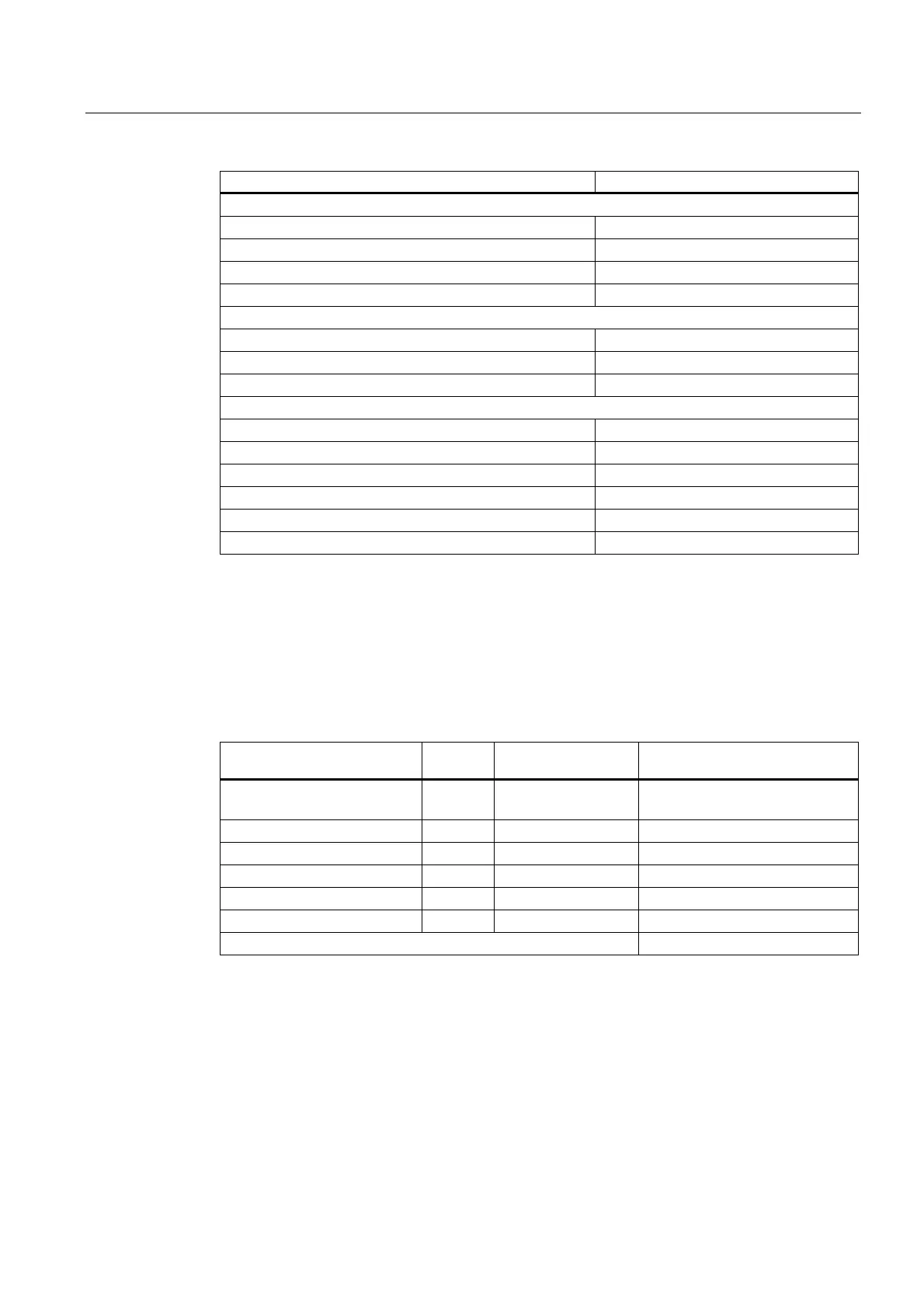
Component Typical current consumption [A
DC
]
Double Motor Modules
2 x 3 A (+ 2 x DRIVE-CLiQ; + 2 x brake) 1,15
2 x 5 A (+ 2 x DRIVE-CLiQ; + 2 x brake) 1,15
2 x 9 A (+ 2 x DRIVE-CLiQ; + 2 x brake) 1,15
2 x 18 A (+ 2 x DRIVE-CLiQ; + 2 x brake) 1,3
Sensor Modules Cabinet
SMC 10 0,25
SMC 20 0,25
SMC 30 0,33
Sensor Modules External
SME 20 0,19
SME 25 0,19
SME 120 0,24
SME 125 0,24
Supplementary system components
Braking Module 0,5
The details apply to Motor Modules / Line Modules with internal/external heat dissipation.
5.6.4 Calculation of the 24 VDC Power Requirement Example
Table 5-21 Example of 24 V DC current requirements
Component Number Current consumption
[A]
Total current consumption [A]
NCU7x0
8 digital outputs
1
8
2,00
0,01
2,00
0,08
Active Line Module 36 kW 1 1,50 1,50
Motor Module 18 A 2 0,85 1,70
Motor Module 30 A 3 0,90 2,70
SMC 5 0,25 1,25
Brake 5 1,10 5,50
Total: 14,73
The following conditions should be considered for the configuring:
● The line infeed of the power supply devices must be tapped in front of the line filter of the
Line Module.
● The line connection of the power supply should be made directly and without additional
switched feeders.
● The dimensioning of the output rated current of the power supply is determined by the
load of the connected consumers.
 Loading...


