Structure of the drive group
2.5 Note for the installation clearance for the connection cables
Guide for the SINUMERIK 840D sl machine configuring
2-22 Manual, 07/2006 Edition, 6FC5397-6CP10-0BA0
2.5 2.5 Note for the installation clearance for the connection cables
2.5.1 General
The arrangement of the components and equipment takes account of
● Space requirements
● Cable routing
● Bending radiuses of the connection cables
MOTION-CONNECT lines, see D21.1 catalog
● Cooling
● EMC
Components are usually located centrally in a cabinet.
The necessary mounting and installation clearances above an below the components can,
under certain circumstances, exceed the minimum clearances specified in the product
documentation.
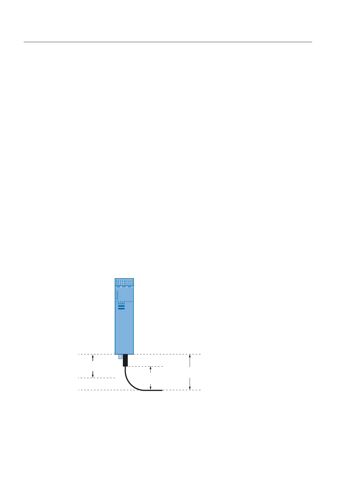
2.5.2 Clearance of the Power Components
The installation clearance is defined by
● Ventilation clearance
● Cable clearance
&RROLQJFOHDUDQFH
PP
&DEOH
FOHDUDQFH
0RXQWLQJ
FOHDUDQFH
Figure 2-20 Clearance in the vicinity of the power components
 Loading...


