Connection of the Components
5.4 Motor Modules Interface Description
Guide for the SINUMERIK 840D sl machine configuring
5-34 Manual, 07/2006 Edition, 6FC5397-6CP10-0BA0
5.4.4 X21/X22 EP Terminals / Motor Module Temperature Sensor Connection
Note
The Motor Module is controlled using the -X21, -X22 terminal block and using DRIVE-CLiQ
at the -X200/201/202/203 terminal block. The detailed function description for the individual
signals and control/status words is contained in the SINAMICS S Parameter Manual.
To enable the Motor Module, the "infeed ready" signal must be connected from the Line
Module.
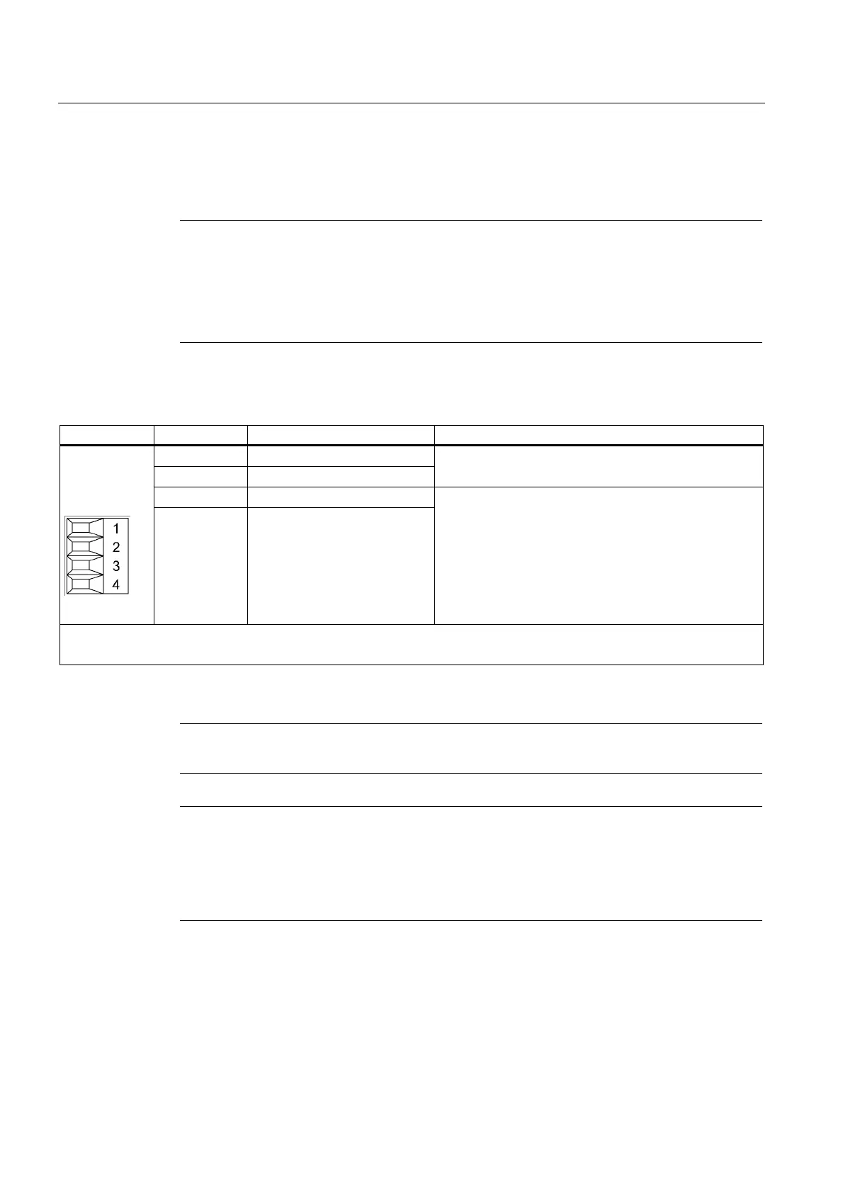
Table 5-14 Terminal block X21/X22
Terminal Function Technical data
1 +Temp
2 -Temp
Temperature sensor connection KTY84–1C130/PTC
3 EP +24 V (Enable Pulses)
4 EP M1 (Enable Pulses)
Supply voltage: 24 V DC (20.4 V - 28.8 V)
Current consumption: 10 mA
Optically isolated input
Signal propagation times:
L → H: 100 μs
H → L: 1000 μs
Max. connectable cross-section 1.5 mm
2
Type: Screw terminal 1 (see Connection Engineering section)
Notice
The KTY temperature sensor/the PTC must be connected with the correct polarity.
Note
The temperature sensor connection is required for motors for which the temperature value is
not transferred using DRIVE-CLiQ.
If the "Safe standstill" function is selected, for operation, ground must be placed at the -
X21:3 24 VDC and the -X21:4 terminal. For cancelation, a pulse suppression will be
activated.
 Loading...


