Home
Siemens
Control Systems
MCP 398C
Siemens MCP 398C Manual
4
of 1
of 1 rating
265 pages
Give review
Manual
Specs
To Next Page
To Next Page
To Previous Page
To Previous Page
Loading...
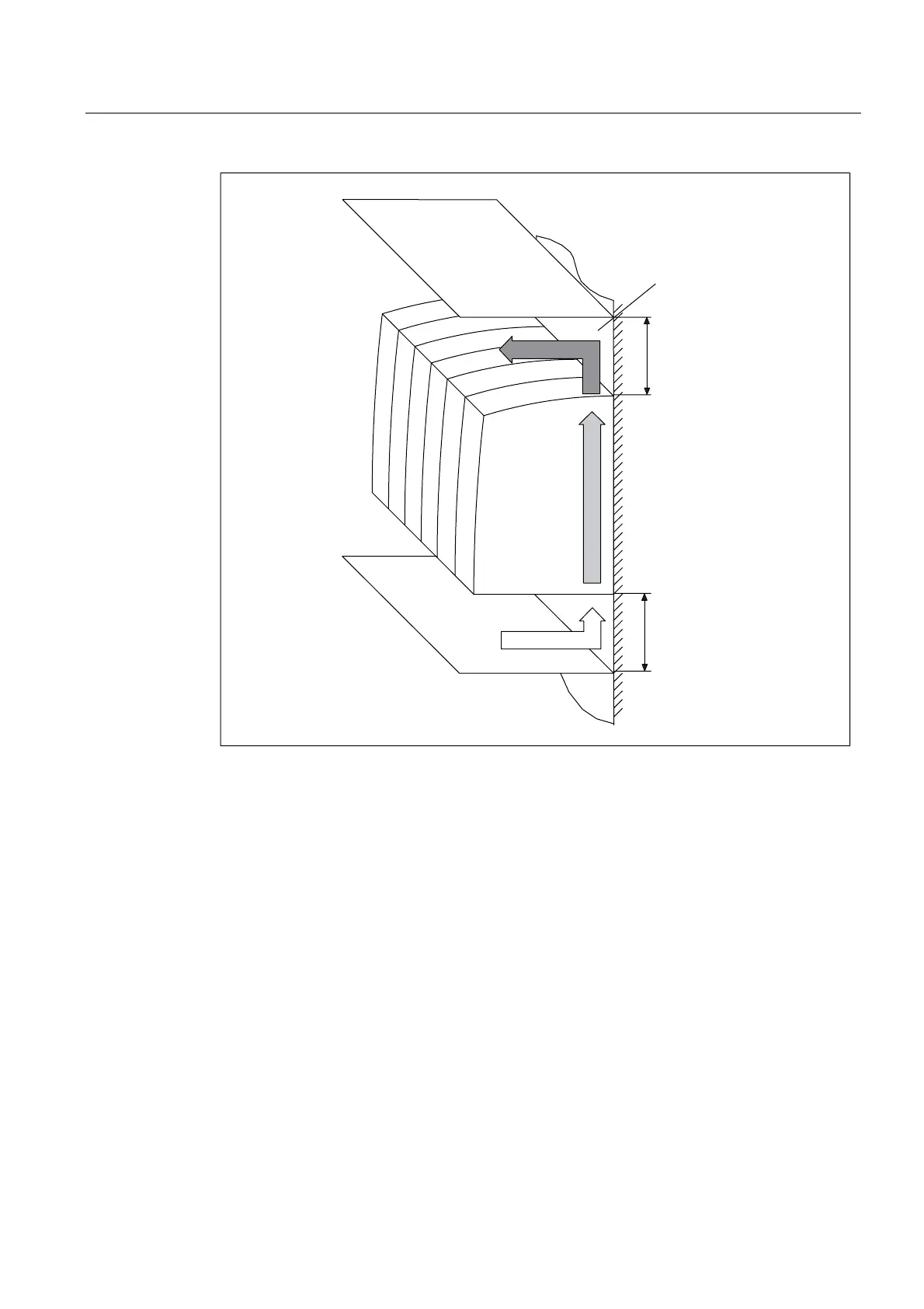
Structure of the drive group
2.6 Heat Dissipation of the Control Cabinet
Guide for the SINUMERIK 840
D sl machine configuring
Manual, 07/2006 Edition, 6FC5397-6CP10-0BA0
2-25
0RXQWLQJVXUIDFH
$LULQWDNH
'LVFKDUJHGDLU
PP
PP
Figure 2-21
Clearances for books
ize
drive line-up w
ith internal air coo
ling
44
46
Table of Contents
Default Chapter
5
Table of Contents
5
1 System Overview
9
Application
9
System Configuration
10
Variants
11
SINAMICS S120 Components
12
SINAMICS S120 / SINUMERIK 840D Sl Component Overview
14
Power Sections
16
HMI User Interface Software
17
2 Structure of the Drive Group
21
Structure
21
Drive Group Structure
21
Single Row Layout
23
Two-Row / Multi-Row Construction
24
Center Infeed (Single Row Construction) for 55/80/120 Kw Line Module
26
Direct Installation of a CU-/NCU-/NX Module on the Line Module
27
Layout of the Components
28
Layout and Fastening of the NCU/ NX Modules
28
Layout of the NX for Single Row Construction Integrated in the Power Unit Group
29
NCU/NX Layout as Offset Solution
30
Current Carrying Capacity of the DC Link Busbar
31
Shield Connection
33
SINAMICS Components Dimension Drawings (Internal Air Cooling)
33
SINAMICS Components Dimension Drawings (External Air Cooling)
37
Shield Connection for Internal Heat Dissipation
41
Note for the Installation Clearance for the Connection Cables
42
General
42
Clearance of the Power Components
42
Heat Dissipation of the Control Cabinet
43
Ventilation Clearances of the SINUMERIK Components
43
General
43
Ventilation
49
Power Loss of the SINUMERIK Components
51
Power Loss of the SINAMICS Components
51
Dimensioning Climate Control Equipment
56
3 NCU/NX Terminal Assignment
57
Commissioning Macros Overview
57
Functions in the Macro
57
Macros for Commissioning
58
Procedure for Calling ACX Macros
60
X122 and X132 Interface Overview
62
NCU 7X0 and Nx1X Terminal Assignment
65
4 Safety Integrated
69
SINAMICS Safety Integrated
69
Control of the "Safe Standstill" Safety Function
69
Safe Brake Control (SBC)
76
SINUMERIK Safety Integrated
77
Fundamentals
77
Connection to Monitoring Channels
77
5 Connection of the Components
85
Power Supply Interface Variants
85
Ways of Connecting the Line Supply
85
Operation of the Line Connection Components on the Supply Network
86
Operating Line Connection Components Via an Autotransformer
87
Operating Line Connection Components Via an Isolating Transformer
88
Line Connection Via a Ground-Fault Circuit Interrupter
89
Line Contactor Control
92
Line Contactor Control for Line Modules Without DRIVE-Cliq Interface
92
Line Contactor Control for Line Modules with DRIVE-Cliq Interface
94
Line Contactor Control Commissioning Using an Example
94
Line Modules Interfaces Description
97
Line Modules Overview
97
Active Line Modules with Internal Air Cooling
100
Overview
100
Connection Example
101
X1 Line Connection
102
Active Line Module X21 EP Terminals
103
Active Line Module X24 24 V Terminal Adapter
104
X200-X202 DRIVE-Cliq Interfaces
105
24 V Busbar
105
Active Line Module DC Link Busbar
105
Meaning of the Leds on the Active Line Module
106
Smart Line Modules (5 Kw und 10 Kw) with Internal Air Cooling
107
Overview
107
Connection Example
108
X1 Line Connection
109
X21 Terminals: Smart Line Module
109
X22 Terminals: Smart Line Module
111
X24 24 V Terminal Adapter
112
Busbar
112
Smart Line Module DC Link Busbar
113
Meaning of the Leds on the Smart Line Module
113
Motor Modules Interface Description
114
Overview
114
Connection Examples
115
Motor/Brake Connection
116
X21/X22 EP Terminals / Motor Module Temperature Sensor Connection
118
X200-X203 DRIVE-Cliq Interface
120
Meaning of the Leds on the Motor Module
120
DRIVE-Cliq Topologies
122
DRIVE-Cliq Wiring
122
NX10/15 Wiring
123
Connectable DRIVE-Cliq Components
125
Electronics Power Supply
126
External Power Supply (SITOP Modular)
126
Selection of the Power Supply Devices
127
24 V Current Consumption of the Components
128
Calculation of the 24 VDC Power Requirement Example
129
Assignment of the Power Supply to Other Components
130
Overcurrent Protection
132
Line Formation
133
Power Supply Connection Example
135
Control Supply Module (CSM)
136
Connection Example
137
Criteria for the Protection, Line Formation and Monitoring
138
Interconnection of the Voltage Output for the CSM
139
Control Supply Module Power Supply - Connection Example
142
Cable Lengths
143
General Information
143
Cable Shielding and Routing
143
Equipotential Bonding
146
Protective Ground Connection
146
Motor Connection
147
Motor Connection Power Cables
147
Connection Examples
149
Motor/Brake Connection
150
X21/X22 EP Terminals / Temperature Sensor Connection Motor Module
152
Sensor Systems Connection
153
Introduction
153
Description
154
X200-X203 DRIVE-Cliq Interface
156
Sensor Connections
156
Brake Connection
158
General Notes
158
Connection of the Brake Directly on the Motor Module
158
Connection of the Brake Using Interface Relay
160
Brake Control
161
Voltage Protection Module (VPM)
166
6 Signal Interconnection
169
Application 1
170
Application 2
170
Application 3
172
Application 4
172
Application 5
174
Application 6
174
Application 7
177
7 Typical Circuit Diagrams
189
Connection Notes, Technical Data, Device Selection
189
Functional Description of the Typical Circuit Diagrams
190
Circuit Manual Group =1
192
Circuit Manual Group =2
200
Circuit Manual Group =3
209
Circuit Manual Group =4
218
Circuit Manual Group =5
227
Circuit Manual Group =6
231
8 Additional Information
245
Distributed Installation
245
Cooling Systems
247
Introduction
247
Internal Air Cooling
247
External Air Cooling
247
Cold Plate
249
9 Activate/Deactivate Drive System
251
Overview of the Status Signals
251
Drive Group with Several Axes
252
ESD Notes
257
Abbreviations
259
B.1 Abbreviations
259
Abbreviations
260
Index
261
Other manuals for Siemens MCP 398C
Operating Manual
940 pages
Diagnostic Manual
1054 pages
Programming Manual
1334 pages
Diagnostics Guide
1002 pages
Operation/Programming
443 pages
Function Manual
2184 pages
Configuration Manual
214 pages
Installation Manual
200 pages
Commissioning Manual
1734 pages
System Manual
44 pages
Equipment Manual
164 pages
Operating Instructions
118 pages
Upgrade Instructions
5 pages
Show more
4
Based on 1 rating
Ask a question
Give review
Questions and Answers:
Need help?
Do you have a question about the Siemens MCP 398C and is the answer not in the manual?
Ask a question
Siemens MCP 398C Specifications
General
Brand
Siemens
Model
MCP 398C
Category
Control Systems
Language
English
Related product manuals
Siemens SINUMERIK ONE MCP 2200
26 pages
Siemens SINUMERIK ONE MCP 2400.c
26 pages
SINUMERIK ONE MCP 2400.4c
940 pages
Siemens SINUMERIK MC
408 pages
Siemens SICAM MIC
92 pages
Siemens COMOS
156 pages
Siemens SICAM RTU
260 pages
Siemens SIMATIC PCS 7
240 pages
Siemens SINUMERIK 828D
926 pages
Siemens Climatix Series
244 pages
Siemens SINUMERIK 840D sl
940 pages
Siemens SIMATIC PCS 7 SMART
210 pages
 Loading...


