Structure of the drive group
2.6 Heat Dissipation of the Control Cabinet
Guide for the SINUMERIK 840D sl machine configuring
2-32 Manual, 07/2006 Edition, 6FC5397-6CP10-0BA0
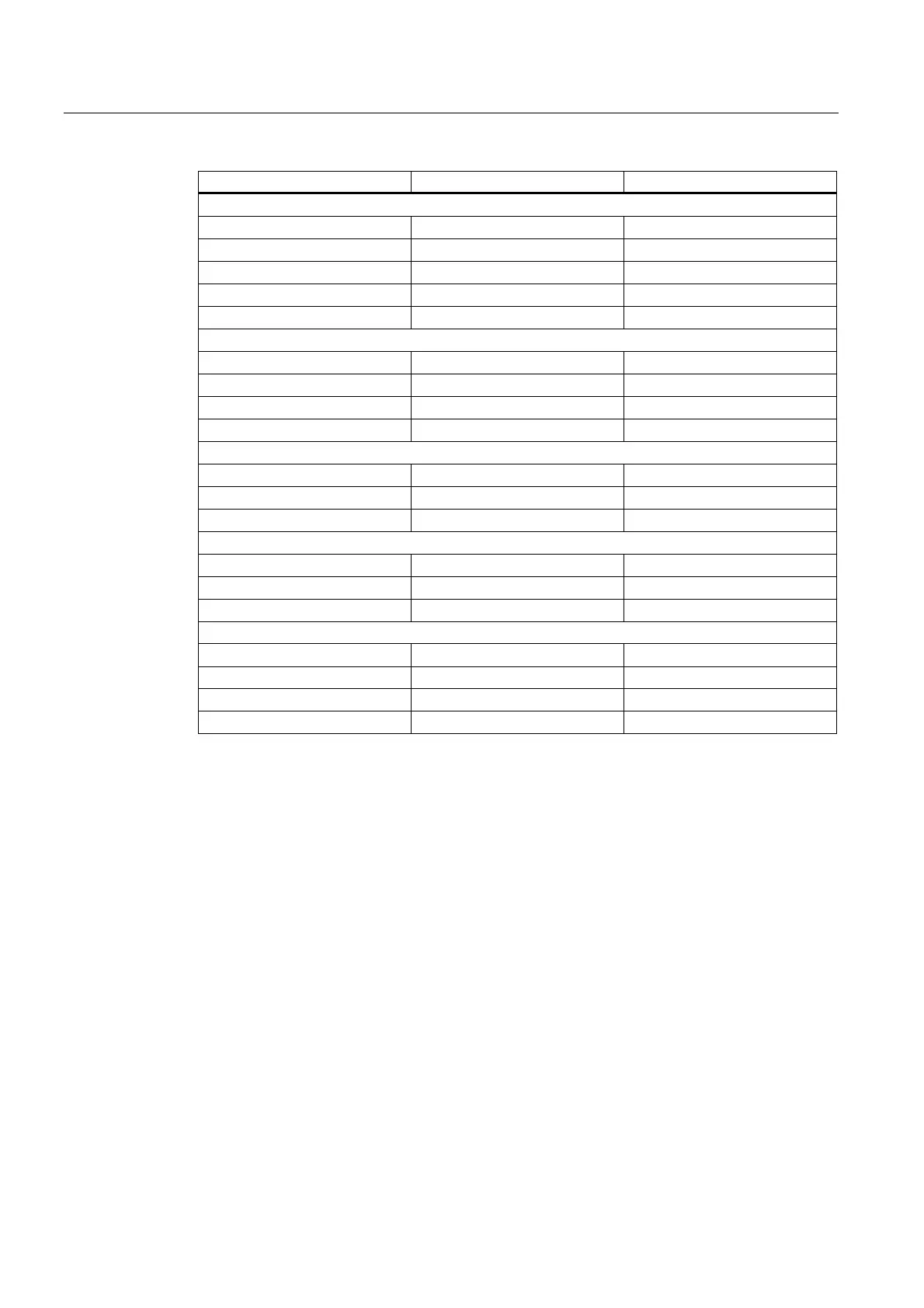
Unit Power loss
Line reactors for Active Line Modules
16 kW W 170
36 kW W 250
55 kW W 350
80 kW W 450
120 kW W 590
Line reactors for Smart Line Modules
5 kW W 62
10 kW W 116
16 kW W 110
36 kW W 170
Sensor Modules
SMC10 W < 10
SMC20 W < 10
SMC30 W < 10
Additional system components
TM15 W < 3
TM31 W < 10
TM41 W 10
DC link components
Braking Module W 20
Capacitor Module W 25
Control Supply Module W < 105
Voltage Clamping Module W 50
The sum of the losses of the various power components (Active Line Module, Smart Line
Module, Motor Module) is calculated from the power losses (following table) and electronic
losses (next table but one).
 Loading...


