Safety Integrated
4.2 SINUMERIK Safety Integrated
Guide for the SINUMERIK 840D sl machine configuring
4-10 Manual, 07/2006 Edition, 6FC5397-6CP10-0BA0
Signal assignment and significance
Part of the signal assignment and significance for the PROFIsafe modules is explained in the
following section:
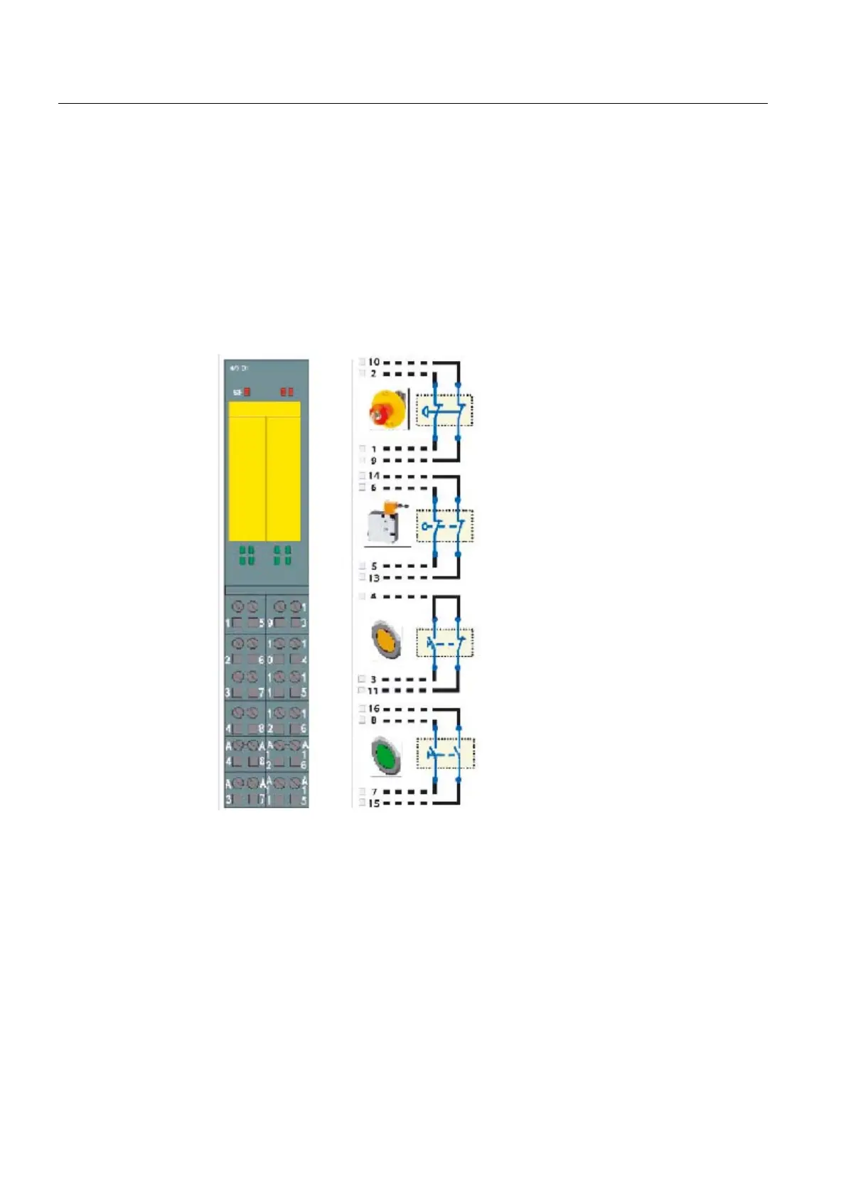
4/8 F-DI 24 VDC PROFIsafe electronic module
The safety-related I/O input signals are connected to this module. These sensors in the
example are optionally exclusive OR with two break contacts (emergency stop activator and
protective door interlocked state), i.e. provided with a break contact and a make contact
(agreement button) or with two make contacts (<drive on> button).
All of the sensor signals are connected through two channels.
96
96
',
',
96
96
',
',
96
',
',
96
96
',
',
(PHUJHQF\VWRS
7\SH%UHDNFRQWDFW
3URWHFWLYHGRRUFORVHG
DQGORFNHG
7\SH%UHDNFRQWDFW
$JUHHPHQWEXWWRQ
7\SH([FOXVLYH25EUHDN
PDNHFRQWDFW
'ULYHV2Q
7\SH0DNHFRQWDFW
Figure 4-6 Signal assignment, electronics module, 4/8F-DI, 24 VDC, PROFIsafe
Meaning and use of the individual signals
Emergency stop activator [F-DI terminal 1 (channel 0), terminal 9 (channel 4)]
Signal state channel 0 = "1" and channel 4 = "1":
Emergency stop activator not pressed.
Signal state channel 0 = "0" and channel 4 = "0":
Emergency stop activator pressed.
 Loading...


