Connection of the Components
5.2 Line Contactor Control
Guide for the SINUMERIK 840D sl machine configuring
Manual, 07/2006 Edition, 6FC5397-6CP10-0BA0
5-11
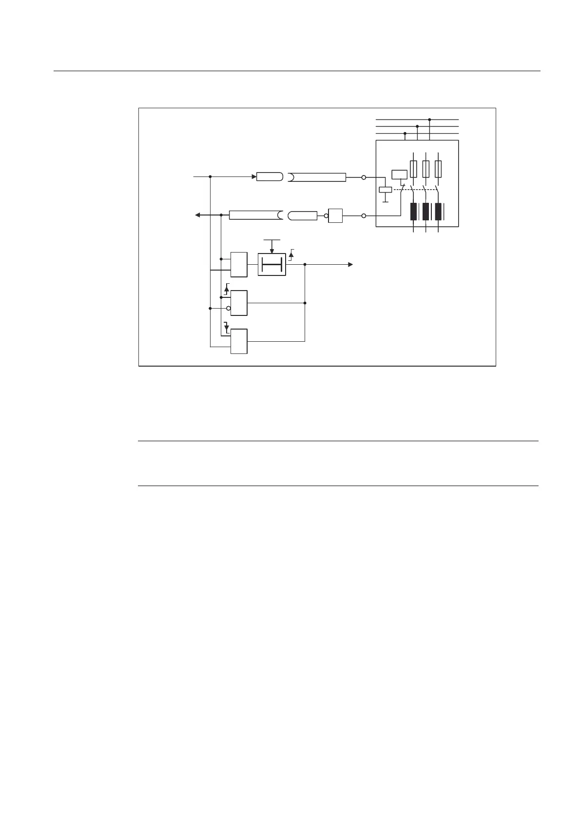
$FWLYH/LQH0RGXOH
r0863.1
p0744 = 0863.1
L1
L2
L3
r0723.7
p0860 = 0723.7
DI/DO 14
X132.10
DI 7
X132.4
p728.8 = 1
24 V
1
p0861 =
100 ms
=1
<1>
T
&
&
0
/LQHFRQQHFWLRQ
)IDXOW
/LQHFRQWDFWRUIHHGEDFNPLVVLQJ
$VRXWSXW
&RQWUROFRQWDFWRU
/LQHFRQWDFWRU
IHHGEDFN
7KHFXUUHQWFDUU\LQJFDSDFLW\RIWKH
RXWSXWVPXVWEHREVHUYHG$QDX[LOLDU\
FRQWDFWRUPD\QHHGWREHXVHG
!
/LQHFRQWDFWRU
FORVHG
Figure 5-8 Line Contactor Control
Commissioning steps:
Note
If the current carrying capacity of the digital output could be exceeded, an auxiliary contactor
may possibly be used (refer to the Equipment Manual for Booksize Power Units)!
1. Connect control contact of the line contactor to DI/DO 14.
2. Parameterize DI/DO 14 as output (p0728.14 = 1).
3. Interconnect (BI: p0744 = r0863.1) DI/DO 14 with "control contactor" signal (r0863.1).
4. Connect the feedback contact of the line contactor to DI 7.
5. Interconnect (BI: p0860 = r0723.7) p0860 with the inverted input signal (p0723.7).
6. Enter the monitoring time of the line contactor (p0861 = 100 ms).
 Loading...


