Configuration using Web Based Management and Command Line Interface
4.3 The X-300/X-400 menu
SCALANCE X-300 / X-400
82 Configuration Manual, 10/2014, C79000-G8976-C187-22
Signal Redundancy Lost by Fault LED (HRP only)
If the check box is selected, a loss of HRP redundancy is indicated by the fault LED of the
redundancy manager and signaled by the fault signaling contact. The loss of redundancy of
a standby link is indicated by the standby slave with the fault LED and the fault signaling
contact. In the factory settings, this function is enabled.
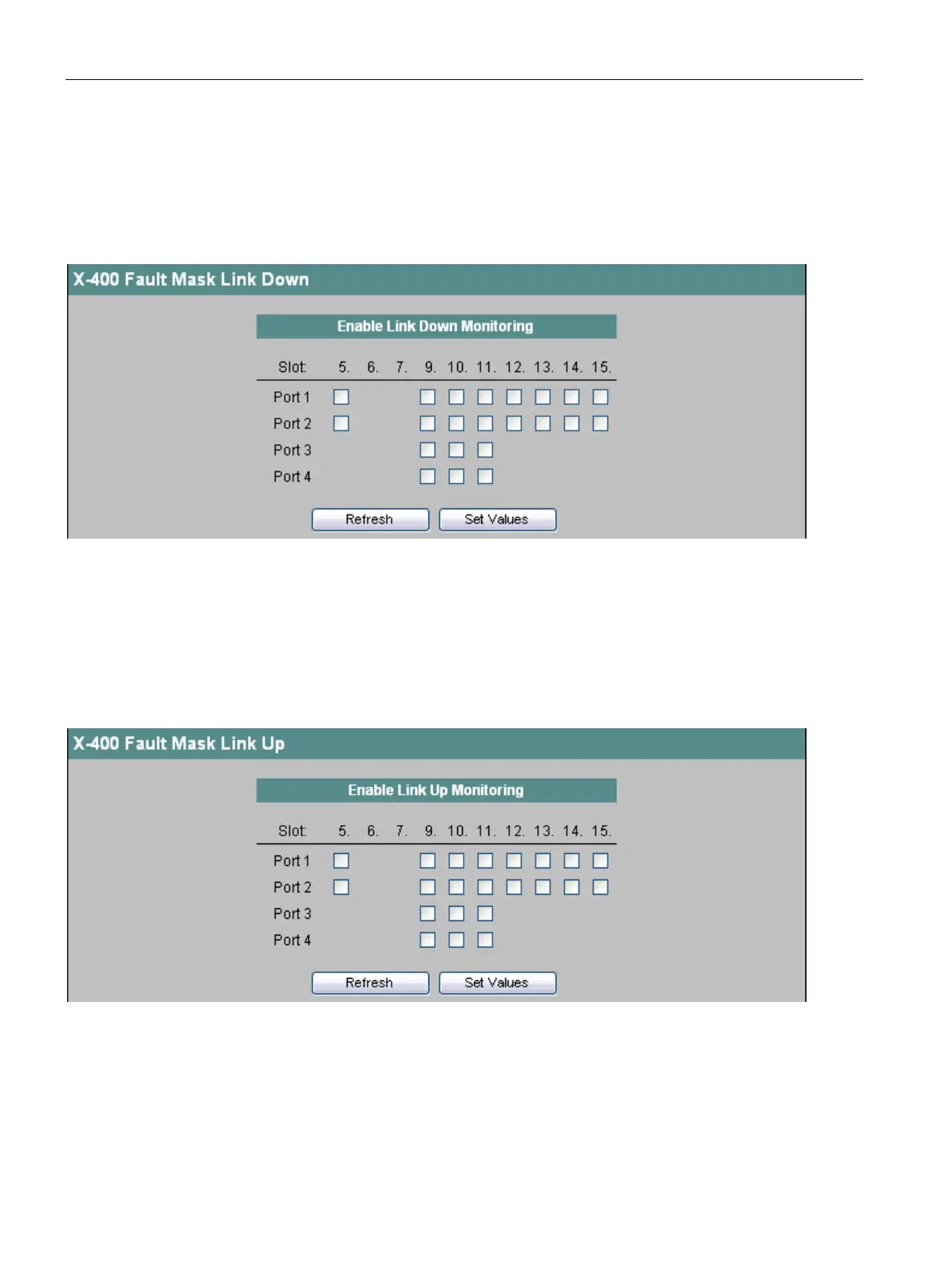
Figure 4-22 X-400-Fault Mask Link Down
Enable Link Down Monitoring
Select the check boxes of the slots / ports whose connection status you want to monitor. If
link monitoring is activated, an error is signaled when there is no valid link at this port
because, for example, the cable is not plugged in or the connected device is turned off.
An error/fault can be signaled in the following ways depending on the configuration of the IE
switch: Signaling contact, fault LED, SNMP trap, E-mail, entry in the log table, syslog.
Figure 4-23 X-400 Fault Mask Link Up
Enable Link Up Monitoring
Select the check boxes of the slots / ports whose connection status you want to monitor. If
link monitoring is activated, an error is signaled when there is a valid link at this port
because, for example, the cable should not be plugged in.

 Loading...


