Configuration using Web Based Management and Command Line Interface
4.1 General information on Web Based Management and Command Line Interface
SCALANCE X-300 / X-400
36 Configuration Manual, 10/2014, C79000-G8976-C187-22
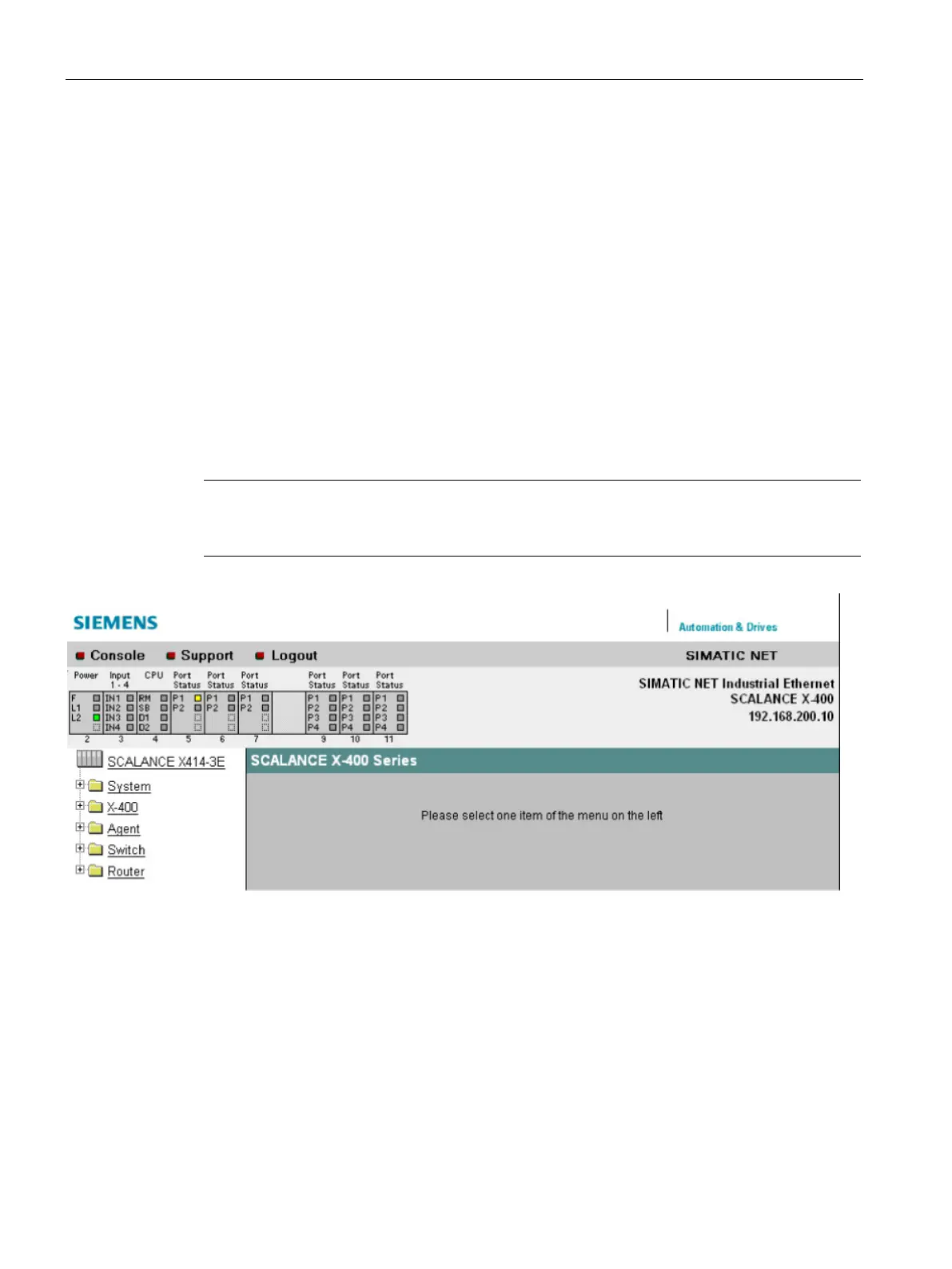
The LED simulation of Web Based Management (WBM)
Display of the operating state
Each component of an IE switch has one or more LEDs that provide information on the
operating state of the device. Depending on its location, direct access to the IE switch may
not always be possible. Web Based Management therefore displays simulated LEDs.
The upper quarter of the screen displays a schematic representation of the IE Switch X-300
or the IE Switch X-400 with the existing modules and corresponding LEDs. The traffic display
is not represented realistically (the LEDs do not flash). The meaning of the LED displays is
described in the operating instructions "Industrial Ethernet Switches SCALANCE X-300" or
operating instructions "Industrial Ethernet Switches SCALANCE X-400".
If you click on the labels above the symbolically displayed modules, you can change the
display mode (LEDs DM or D1/D2) of the display in the simulation just as with the button on
the device.
Note
The media module extender of the SCALANCE X414
-
3E is displayed in the simulation only if
it has at least one module inserted.
Figure 4-2 SCALANCE X414-3E LED simulation
 Loading...


