Mounting and connecting
4.4 Connecting the connection box
Mobile Panel 277 RO
48 Operating Instructions, 10/2015, A5E36824256-AA
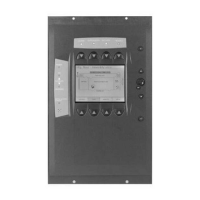
The following figure shows how to connect the power supply to the connection box PN Plus.
The abbreviations in the figure are defined as follows:
● PE stands for protective conductor.
● M24 stands for ground.
● P24 stands for +24 VDC.
Please refer to the technical data for the supply voltage requirements.
Personal injury and damage to property
Configure the 24 VDC supply of the Mobile Panel 277 RO correctly. Otherwise there is a
risk that the components of your automation system will be damaged and that people will
be injured.
Use only voltage generated as safety extra-low voltage (SELV) for the 24 VDC supply of
the Mobile Panel 277 RO.
Safe electrical separation
Use only power supply units with safety isolation complying with IEC 60364-4-41 or
HD 384.04.41 (VDE 0100, Part 410), for example according to the PELV standard, for the
24 VDC supply.
The supply voltage must be
within the specified voltage range. Otherwise there is a risk that
the HMI device will malfunction.
Applies to non-isolated system design:
Connect the connection for GND 24 V from the 24 V power supply output to equipotential
bonding for uniform reference potential.

 Loading...
