Power Supply Modules
3-23
S7-400, M7-400 Programmable Controllers Module Specifications
A5E00069467-07
3.8 Power Supply Modules
PS 407 10A; (6ES7407-0KA01-0AA0) and
PS 407 10A R; (6ES7407-0KR00-0AA0)
Function
The power supply modules PS 407 10A (standard) and PS 407 10A R
(redundancy-capable, see Section 3.2) are designed for connection to an AC line
voltage of 85 to 264 V or DC line voltage of 88 to 300 V and supply 5 VDC/10 A
and 24 VDC/1 A on the secondary side.
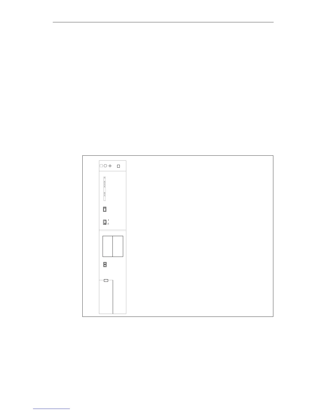
Controls and Displays of the PS 407 10A and thge PS 407 10A R
• FMR pushbutton (Failure Message Reset)
• Standby switch (does not cut off mains)
• Switches BATT. INDIC.
2 BATT, OFF, 1 BATT
• Battery compartment
• 3-pin plug-in power connector
• Fixing screw
• LEDs INTF,
BAF, BATT1F, BATT2F,
5 VDC, 24 VDC
PS 407 10A
407-0KR00-0AA0
X2
34
1
FMR
BATT. INDIC.
2 BATT
1 BATT
OFF
+
–
+
–
2
INTF
BAF
BATTF
5 VDC
24 VDC
BATTF
BATT.1 BATT.2
Under cover
• Fixing screw
Figure 3-4 Controls and Displays of the PS 407 10A and PS 407 10A R