IM 463-2
7-10
S7-400, M7-400 Programmable Controllers Module Specifications
A5E00069467-07
7.6 Configuring S5 Modules for Operation in the S7-400
You configure the S5 modules using STEP 7. See the description of STEP 7 or the
online help function for details of how to proceed.
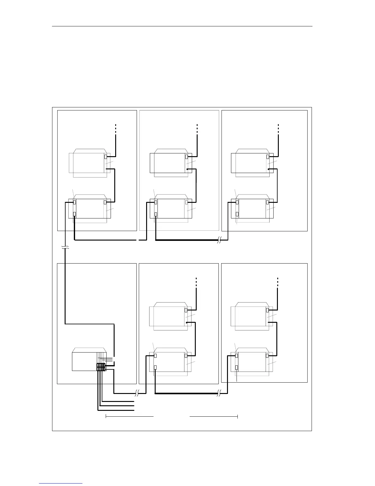
The following figure shows a possible connection of CRs and EUs via the IM 463-2
and IM 314.
IM 312-3
IM 300-3
IM 314
IM 312-3
IM 300-3
IM 314
IM 312-5
IM 314
All 721 connecting cables
further EU 184U,
EU 187U (central)
IM 312-3
IM 300-3
IM 314
IM 312-5
IM 300-5
IM 314
Terminating connector 760-1AA11
All 721 connecting cables
To further S5 expansion units (distributed) (max. 4 per IM 463-2)
max. 600 m
S7-400
Central mounting rack
IM 300-5
IM 463-2
S5
expansion
unit
Terminating connector 760-1AA11
S5
expansion
unit
S5
expansion
unit
S5
expansion
unit
S5
expansion
unit
S5
expansion
unit
S5
expansion
unit
S5
expansion
unit
S5
expansion
unit
S5
expansion
unit
Figure 7-3 Connection Variant for CCs and EUs via the IM 463-2 and IM 314