Parameter Sets for Signal Modules
A-4
S7-400, M7-400 Programmable Controllers Module Specifications
A5E00069467-07
A.2 Parameters of the Digital Input Modules
Parameters
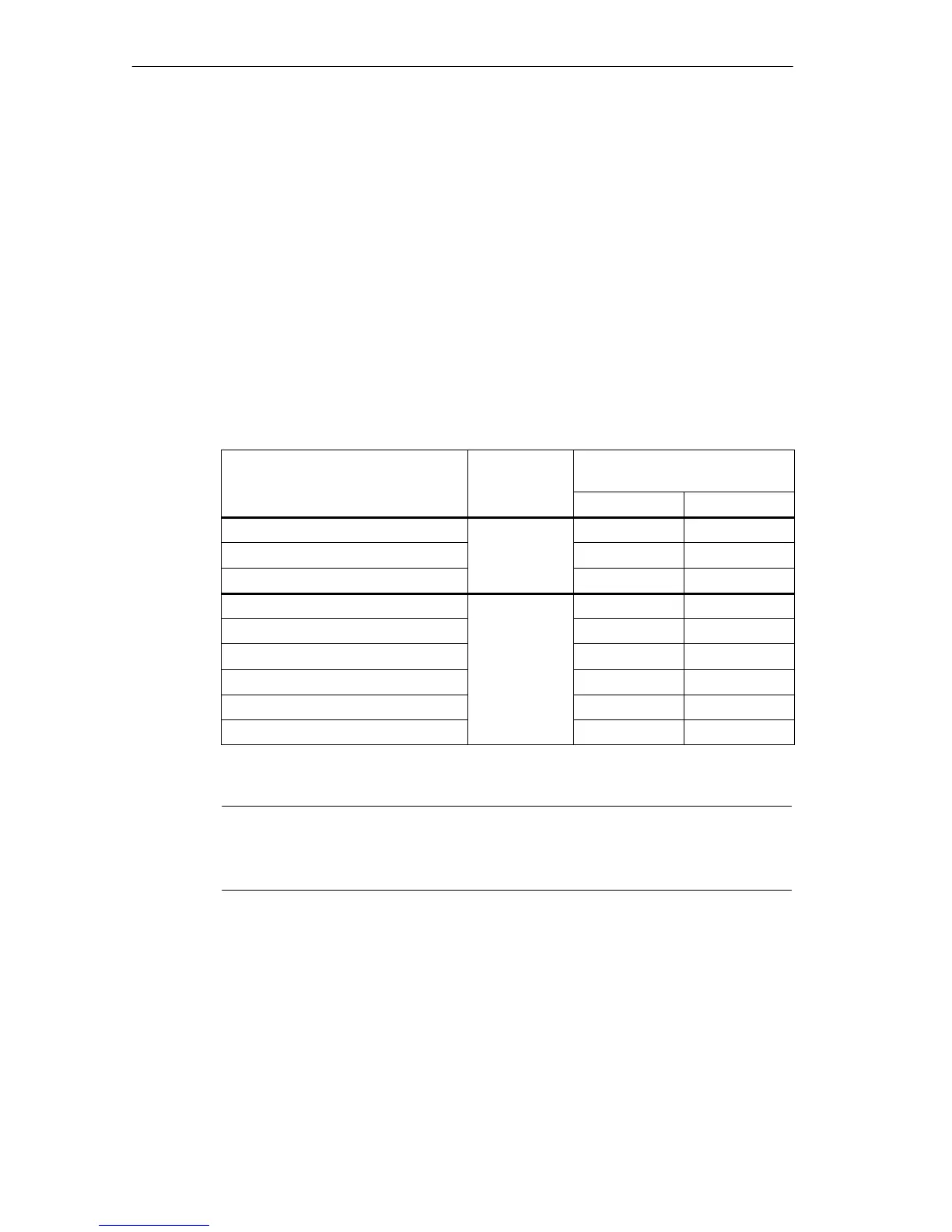
The table below contains all the parameters you can set for digital input modules.
You will see which parameters you can modify from the list:
• in STEP 7
• with SFC 55 ”WR_PARM”
The parameters set with STEP 7 can also be transferred to the module with SFCs
56 and 57 (refer to the STEP 7 manuals).
Table A-2 Parameters of the Digital Input Modules
Parameter
Data Record
No.
Parameters Can Be Assigned
with ...
... SFC 55 ... STEP 7
Destination CPU for interrupts No Yes
Input delay
0
No Yes
Diagnostics No Yes
Hardware interrupt enable Yes Yes
Diagnostic interrupt enable Yes Yes
Reaction to error*
Yes Yes
Hardware interrupt with rising edge
1
Yes Yes
Hardware interrupt with falling edge Yes Yes
Substitute “1”* Yes Yes
* Only in 6ES7421-7BH00-0AB0
Note
If you want to enable the diagnostic interrupt in the user program in data record 1,
you must enable the diagnosis in data record 0 beforehand using STEP 7.
Structure of Data Record 1
The figure below shows the structure of data record 1 (bytes 0, 1, 2 and 3) for the
parameters of the digital input modules.
You enable a parameter by setting the corresponding bit to “1”.