Interface Submodules
13-28
S7-400, M7-400 Programmable Controllers Module Specifications
A5E00069467-07
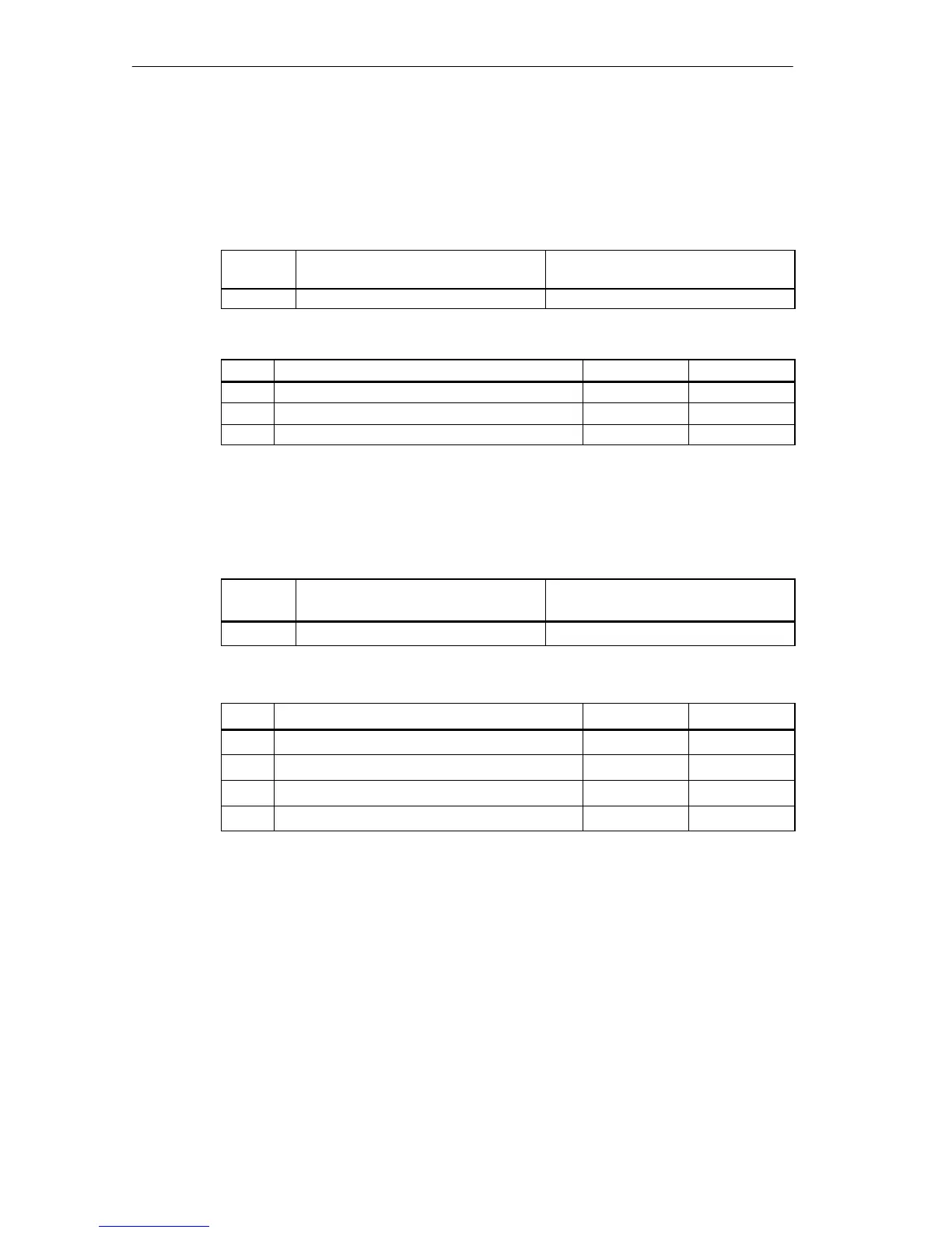
Interrupt Register
The cause of the interrupt is stored in this register. Tables 13-28 and 13-29 give an
overview of the interrupt register.
Table 13-28 Offset Address for the Interrupt Register (IF 961-DIO)
Offset
Address
Function Remarks
3 Interrupt register Read only
Table 13-29 Meaning of the Bits in the Interrupt Register (IF 961-DIO)
Bit
Function = 0 = 1
2
0
Level change at DI channel 0 No Yes
: : : :
2
7
Level change at DI channel 7 No Yes
Interrupt Enable Register
Tables 13-30 and 13-31 give an overview of the interrupt enable register.
Table 13-30 Offset Address for the Interrupt Enable Register (IF 961-DIO)
Offset
Address
Function Remarks
4 Interrupt enable register Read/write
Table 13-31 Meaning of the Bits in the Interrupt Enable Register (IF 961-DIO)
Bit
Function = 0 = 1
2
0
Reserved
: :
2
6
Reserved
2
7
Interrupt Disabled Enabled

 Loading...


