Digital Modules
4-25
S7-400, M7-400 Programmable Controllers Module Specifications
A5E00069467-07
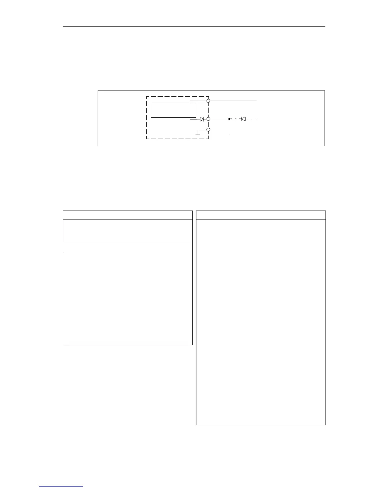
Terminal Assignment Diagram for Redundant Supply of Sensors
The figure below shows how sensors can additionally be supplied by means of Vs
with a redundant voltage source – for example, via another module).
Vs
M
L+
1 L+
2 L+
to the sensors
±
Digital input
module
Short-circuit-
proof driver
Figure 4-5 Terminal Assignment Diagram for the Redundant Supply of Sensors of the
SM 421; DI 16 24 VDC
Technical Specifications of the SM 421; DI 16 24 VDC
Dimensions and Weight
Dimensions W H D
(in millimeters)
25 290 210
Weight Approx. 600 g
Data for Specific Module
Number of inputs 16
Length of cable
• Unshielded
input delay
– 0.1 ms
– 0.5 ms
– 3 ms
Max. 20 m
Max. 50 m
Max. 600 m
• Shielded
input delay
– 0.1 ms
– 0.5 ms
– 3 ms
Max. 30 m
Max. 70 m
Max. 1000 m
Voltages, Currents, Potentials
Rated supply voltage of the
electronics and sensor L+
24 VDC
• Reverse polarity protection Yes
Number of inputs that can be
triggered simultaneously
16
Isolation
• Between channels and
backplane bus
Yes
• Between channels and
power supply of the
electronics
No
• Between the channels Yes
– In groups of 2
Permitted potential difference
• Between the different
circuits
75 VDC, 60 VAC
Insulation tested with
• Channels against
backplane bus and load
voltage L+
500 VDC
• Channel groups between
themselves
500 VDC
Current consumption
• From the backplane bus
• From the power supply L+
Max. 130 mA
Max. 120 mA
Power dissipation of the
module
Typ. 5 W



 To Next Page