Power Supply Modules
3-11
S7-400, M7-400 Programmable Controllers Module Specifications
A5E00069467-07
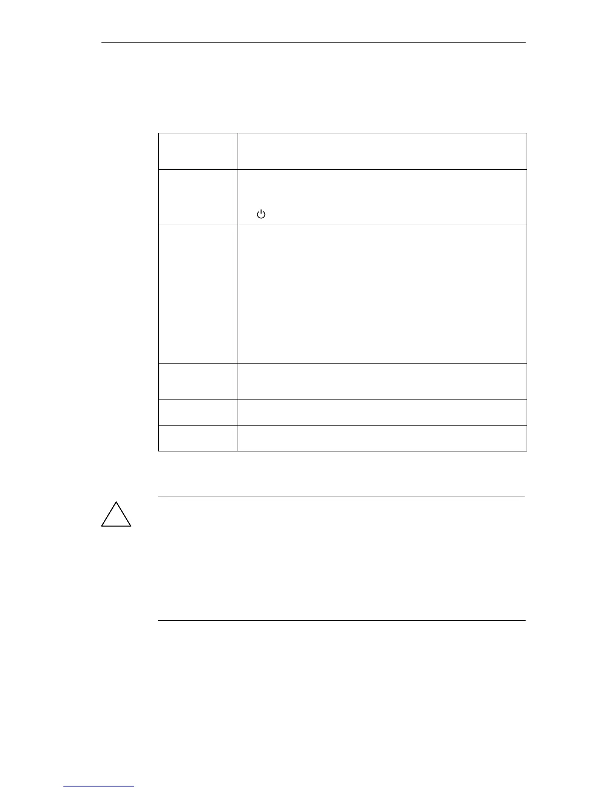
Function of the Operator Controls
Table 3-6 Function of the operator controls of the power supply modules
FMR momentary-
contact pushbut-
ton
For acknowledging and resetting a fault indicator after correcting the
fault
Standby switch Switches the output voltages (5 VDC/24 VDC) to 0 V by intervening in
the control loop (no mains disconnection).
• I : Output voltages at rated value
• : Output voltages 0 V
BATT INDIC
switch
Used for setting LEDs and battery monitoring
Where one battery can be used (PS 407 4A, PS 405 4A):
• OFF: LEDs and monitor signals inactive
• BATT: BAF/BATTF LEDs and monitor signals active
Where two batteries can be used (PS 407 10A, PS 407 20A, PS
405 10A, PS 405 20A):
• OFF: LEDs and monitor signals inactive
• 1 BATT: Only BAF/BATT1F LEDs (for battery 1) active.
• 2 BATT: BAF/BATT1F/BATT2F LEDs (for batteries 1 and 2) active.
Voltage selector
(if present)
For setting the primary voltage (120 VAC or 230 VAC), protected by its
own cover.
(Please note the following information)
Battery compart-
ment
For backup battery (batteries)
Power connec-
tion
3-pin connector for line voltage connection (do not plug in or remove
when power is on).
!
Caution
One of the following power supply modules could be damaged:
Power supply module PS 407 4A (6ES7407-0DA00-0AA0)
Power supply module PS 407 20A (6ES7407-0RA00-0AA0)
If you set the voltage selector to 120 V on these AC power supply modules and
connect the power supply modules to a 230 V power system, it might damage the
power supply modules. Warranty is excluded in such a case.
Set the voltage selector on these AC power supply modules to the line voltage.