Power Supply Modules
3-8
S7-400, M7-400 Programmable Controllers Module Specifications
A5E00069467-07
3.4 Controls and Indicators
Introduction
The power supply modules of the S7-400 have essentially the same controls and
indicators.The main differences are:
• Not all the power supply modules have a voltage selector.
• Power supply modules with a backup battery have an LED (BATTF) that
indicates an empty, defective, or missing backup battery.
Power supply modules with two redundant backup batteries have two LEDs
(BATT1F and BATT2F) to indicate empty, defective or missing backup batteries.
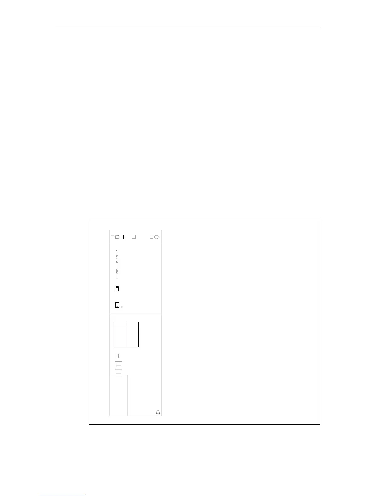
Operator Controls and Indicators
Figure 3-1 shows you an example of a power supply module (PS 407 20A) with two
(redundant) backup batteries. The LEDs are at the top left of the module front
plate.
• FMR pushbutton (Failure Message Reset)
• Standby switch (does not cut off mains)
• Switches BATT. INDIC.
2 BATT, OFF, 1 BATT
• Voltage selector (if present)
• Battery compartment
• 3-pin plug-in power connector
• Fixing screw
• Fixing screws
• LEDs INTF,
BAF, BATT1F, BATT2F, 5 VDC, 24 VDC
5 VDC, 24 VDC
PS 407 20A
407-0RA00-0AA0
X2
34
1
FMR
BATT. INDIC.
2 BATT
230
VOLTAGE
1 BATT
OFF
INTF
BAF
BATTF
5 VDC
24 VDC
BATTF
2
3
BATT.1 BATT.2
+
–
+
–
Under cover
Figure 3-1 Controls and Indicators on the PS 407 20A Power Supply Module