RS 485 Repeater
10-5
S7-400, M7-400 Programmable Controllers Module Specifications
A5E00069467-07
Terminal Connection Diagram
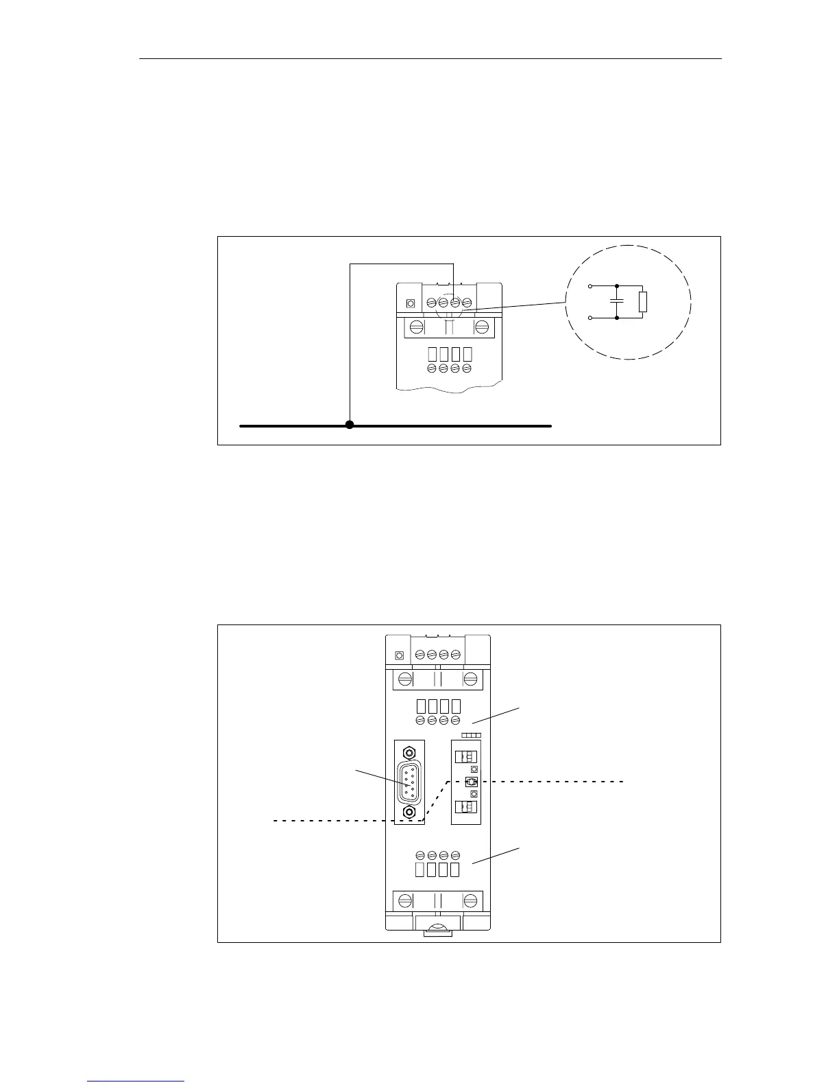
In the case of a repeater configuration with ungrounded reference potential
(ungrounded operation), any interference currents and static charges are
discharged by means of an RC network integrated in the repeater (refer to
Figure 10-1) to the protective conductor.
24 VDC
L+ M PE M 5.2
A1 B1 A1 B1
M
22 nF 10 MΩ
Ground bus
PE
Figure 10-1 RC Network with 10 MΩ for Configuration with Ungrounded Reference Potential
Isolation Between Bus Segments
Bus segment 1 and bus segment 2 are galvanically isolated from each other. The
PG/OP interface is connected internally to the port for bus segment 1. Figure 10-2
shows the front panel of the RS 485 repeater.
24 VDC
L+ M PE M 5.2
SIEMENS
RS 485-REPEATER
ON
A1 B1 A1 B1
A2 B2 A2 B2
PG
OP
DP2
OFF
ON
DP1
Terminals for bus segment 1
Terminals for bus segment 2
PG/OP
interface
Isolation
Figure 10-2 Isolation Between the Bus Segments