Interface Submodules
13-26
S7-400, M7-400 Programmable Controllers Module Specifications
A5E00069467-07
13.6.2 Addressing and Interrupts
Addressing in the M7-300/400-Reserved I/O Address Area
The base address depends on the interface submodule slot in the expansion
module or the programmable module. See the descriptions “M7-300 Expansions”,
“M7-400 Expansions” or the description of the M7-400 programmable modules for
the slot-dependent base address of the interface submodule.
The I/O address is the sum of the base address and the offset address.
The registers and their meanings and the offset addresses are described below.
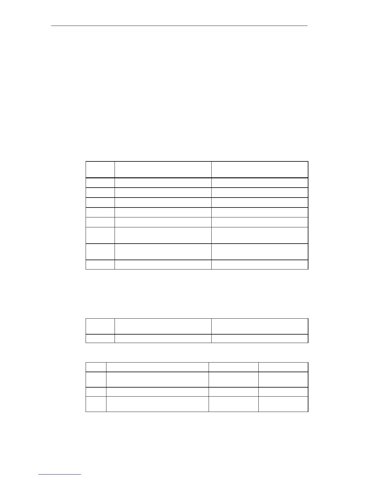
Table 13-21 Offset Address Assignments for the IF 961-DIO Interface Submodule
Offset
Address
Function Remarks
00
H
User data digital input function DI0 - DI7 (Digital Input)
01
H
User data digital output function DO0 - DO7 (Digital Output)
02
H
Acknowledgment register Acknowledge interrupt
03
H
Interrupt register Read cause of interrupt
04
H
Interrupt enable register General enable of interrupt
05
H
Selection register rising edge Interrupt generation at rising edge of
a digital input
06
H
Selection register falling edge Interrupt generation at falling edge of
a digital input
07
H
Mode register Set input delay
Digital Input Function
Tables 13-22 and 13-23 give an overview of the digital input function.
Table 13-22 Offset Address for the Digital Input Function (IF 961-DIO)
Offset
Address
Function Remarks
0 User data digital input function Read only
Table 13-23 Assignment of the Digital Input (DI) Channels to the Bits (IF 961-DIO)
Bit
Function = 0 = 1
2
0
DI channel 0 In the range
-30 V to 5 V
In the range
from 13 V to 30 V
: : : :
2
7
DI channel 7 In the range
-30 V to 5 V
In the range
from 13 V to 30 V