Digital Modules
4-29
S7-400, M7-400 Programmable Controllers Module Specifications
A5E00069467-07
4.9.2 Behavior of the SM 421; DI 16 24 VDC
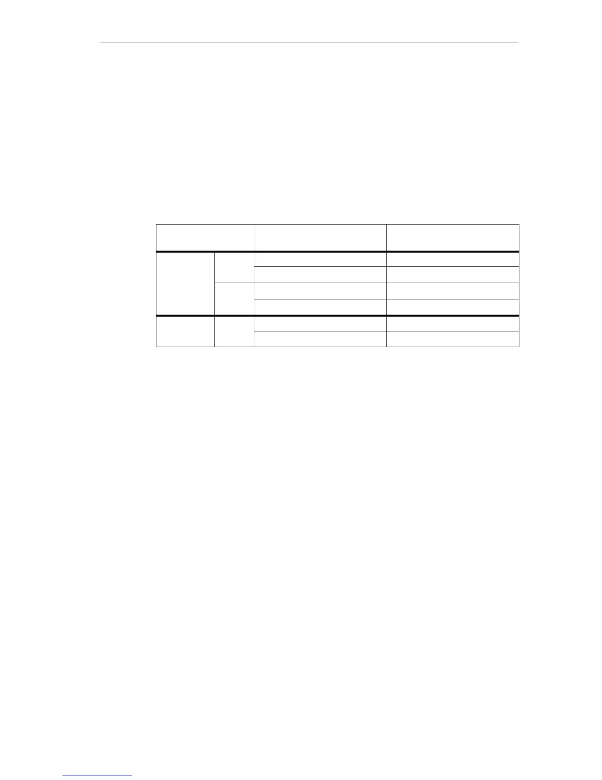
Effect of Operating Mode and Supply Voltage on the Input Values
The input values of the SM 421; DI 16 24 DC depend on the operating mode of
the CPU and on the supply voltage of the module.
Table 4-11 How the Input Values Depend on the Operating Mode of the CPU and on the
Supply Voltage L+ of the SM 421; DI 16 24 VDC
CPU Operating Mode
Power Supply L+
to Digital Module
Input Value of Digital Module
POWER ON RUN
L+ exists Process value
L+ missing 0 signal *
STOP
L+ exists Process value
L+ missing 0 signal*
POWER
–
L+ exists –
OFF
L+ missing –
* Depends on the parameter assignment (see Table 4–12 )
Behavior upon Failure of the Supply Voltage
Failure of the supply voltage of the SM 421; DI 16 24 DC is always indicated by
the EXTF LED on the module. Furthermore, this information is made available on
the module (entry in diagnosis).
Triggering of the diagnostic interrupt depends on the parameter assignment (see
Section 4.9.1).
Short-Circuit of Sensor Supply Vs
Irrespective of the parameter assignment, the corresponding Vs LED goes out if a
short-circuit of the encoder supply Vs occurs.