Interface Submodules
13-48
S7-400, M7-400 Programmable Controllers Module Specifications
A5E00069467-07
13.7.9 Analog Input Function
Analog Input Function
Tables 13-41 ad 13-42 contain an overview of the read and write registers for the
analog input function.
The data format of analog input values is a 16-bit value in two’s complement. You
can see the representation of the digitized measured value in Table 13-43.
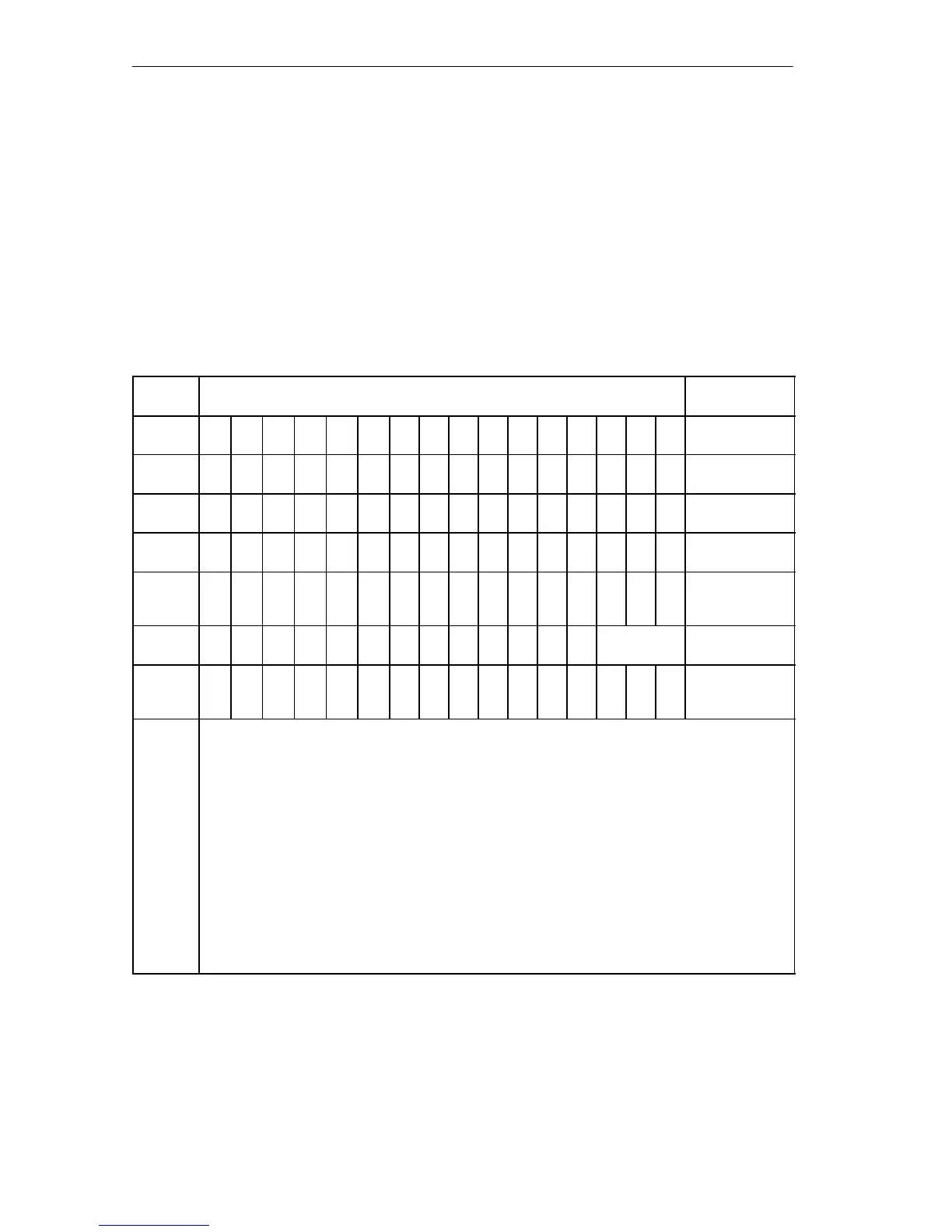
Table 13-41 Meaning of the Input Bits in the Analog Input Function (IF 961-AIO)
Offset
Address
D15
Reading
D0
Remark
00
H
2
15
2
14
2
13
2
12
2
11
2
10
2
9
2
8
2
7
2
6
2
5
2
4
2
3
2
2
2
1
2
0
ADC data
channel 0
02
H
2
15
2
14
2
13
2
12
2
11
2
10
2
9
2
8
2
7
2
6
2
5
2
4
2
3
2
2
2
1
2
0
ADC data
channel 1
04
H
2
15
2
14
2
13
2
12
2
11
2
10
2
9
2
8
2
7
2
6
2
5
2
4
2
3
2
2
2
1
2
0
ADC data
channel 2
06
H
2
15
2
14
2
13
2
12
2
11
2
10
2
9
2
8
2
7
2
6
2
5
2
4
2
3
2
2
2
1
2
0
ADC data
channel 3
08
H
A
C
I
N
T
0 0 0 0 0 0 0 0 0 0 0 ta ta ta Control register 1
0A
H
0 0 0 0 0 0 0 0 0 0 0 0 0
ADC
channel no.
Control register 2
0C
H
0 0 0 0 0 0 0 0 0 0 0 0 0 0
P
F
E
O
C
Status register
ADC
ta = 000
ta = 001
ta = 010
ta = 011
ta = 100
INT
AC = 1
ADC channel no.
ADC = 001
ADC = 010
ADC = 011
ADC = 100
PF = 1
EOC = 1
5.7 ms cycle time of the automatic conversion function
2.8 ms
1.3 ms
600 µs
185 µs
Interrupt enable, INT = 0 = not enabled, INT = 1 = enabled
Automatic conversion of all ADC channels active
Number of the selected ADC channel (in the case of conversion on request)
(individual encoding)
Channel 0
Channel 1
Channel 2
Channel 3
Power failure, no external voltage
End of conversion, end of the analog-digital conversion of the selected channel

 Loading...


